Jump to content

Welcome to RennTech.org Community, Guest

There are many great features available to you once you register at RennTech.org
You are free to view posts here, but you must log in to reply to existing posts, or to start your own new topic. Like most online communities, there are costs involved to maintain a site like this - so we encourage our members to donate. All donations go to the costs operating and maintaining this site. We prefer that guests take part in our community and we offer a lot in return to those willing to join our corner of the Porsche world. This site is 99 percent member supported (less than 1 percent comes from advertising) - so please consider an annual donation to keep this site running.

Here are some of the features available - once you register at RennTech.org

  • View Classified Ads
  • DIY Tutorials
  • Porsche TSB Listings (limited)
  • VIN Decoder
  • Special Offers
  • OBD II P-Codes
  • Paint Codes
  • Registry
  • Videos System
  • View Reviews
  • and get rid of this welcome message

It takes just a few minutes to register, and it's FREE

Contributing Members also get these additional benefits:
(you become a Contributing Member by donating money to the operation of this site)

  • No ads - advertisements are removed
  • Access the Contributors Only Forum
  • Contributing Members Only Downloads
  • Send attachments with PMs
  • All image/file storage limits are substantially increased for all Contributing Members
  • Option Codes Lookup
  • VIN Option Lookups (limited)

Ahsai

Contributing Members
  • Posts

    2,804
  • Joined

  • Last visited

  • Days Won

    10

Everything posted by Ahsai

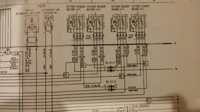
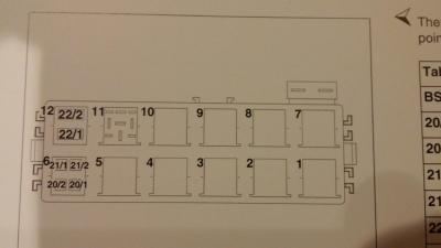
  1. Ok, this is getting more interesting. I assume you meant "0.5v" and not "0.05v" for the O2 signal. If that's true, you are correct that the problem (at least) is at the power supply to the heaters. All the wires you measured are the correct wires. Gray dust on sensor is normal. 1. Check fuse C2 (30A). The power flow is: 12v power->C2->injection/ignition relay ->line "b"->BS21/1->black wire of the O2 sensor heaters black (see the diagram below). In case you blew the fuse while you were measuring. The relay and the fuse are not shown. 2. Turn the key to the last position before cranking like you did when testing 3. Measure the red/white heater wire (connect the black meter probe to a ground point such as the rear lid latch) and you should see ~2v. This is the ground supplied by the DME but it's never 0.00v. If it is, you have a wire break between the heater and the DME. 4. Measure the black heater wire (connect the black meter probe to a ground point) and you should see ~12v. If not, the only connection point between it and the injection/ignition relay is the BS21/1 bridge point located at the rear relay behind the rear seats below the carpet. check the voltage there. In position 6 here. Here I'm assuming your injection relay is good (position 2) since this relay also supplies power to the ignition coils and your car starts find. Depending on what you find, we may need to revisit the relay. 5. Repeat steps 2 to 4 for the postcat sensors (yes postcat) and you should get similar readings. That will help us diagnose it further. 6. Measure the resistance of the heaters. They should be ~10Ohm Let me know what you find and good luck.
  2. Yea, the x2/4 seems to be the next logical choice to check. I have not done it but I expect you need to remove the left side panel lining in Chapter "Group 7 body interior" pdf pages 61 and 62 here. The x2/4 is a white 30pin white connector per the repair manual and you want to check pin #3. Also described here on Renntech. Also, have you checked fuse #A8, which is between the DRL relay and the license plate lights.
  3. We generally use an aluminum based product, but have also used the copper based as well. I like the copper a little better, but copper prices tend to make it more expensive. Thanks John.
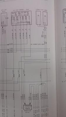
  4. I like xmac's theory. Btw, there's one connector between the bridge plug and the license plate light cable called x2/4 in the diagram below. X2/4 is at the base of the B pillar below the carpet. After x2/4 if you go upstream, it splits into two paths. One goes to the bridge plug and the other goes to the DRL relay so it can get power at either place. If you have DRL and the license lights don't get power, this x2/4 is a suspect. The above is taken from '02 USA car and yours may not be the same.
  5. John, any preference on copper vs nickel based anti seize then?
  6. Welcome to Renntech! Do you have daytime running light? Also are you sure you're looking at the correct fuse? Any recent body work that could break the wires?
  7. Wow, hard to imagine bushings from pedal assembly can create so much drag. Learn something new everyday. Thanks for the update and glad you get it sorted out!
  8. This is getting more interesting. I found this odd though -> "But with the ignition still on I got NO voltage down the two heater wires from the car harness." You disconnected the O2 sensor when making measurements, right? One of the heater wires supplies +ve from the same circuit as the coils/injectors, etc when the other wire is the GROUND supplied by the DME. So one of the wires should have ~12v...Since your car starts so obviously the coils/injectors are getting power but yet the O2 heaters do not? Also when you tested for voltage from the sensor, you used a very low V settting (e.g., DC 2V full scale), right? The voltage produced from an O2 sensor is small at < 1v.
  9. I would not use sealant. As long as the mating surfaces are clean and not galled, the stock gasket is good. You will have more problems if sealant got into the narrow coolant passages.
  10. All right! May take some driving cycles to be 100% sure though to let the O2 sensor tests run and complete. I like your odds though based on your previous codes.
  11. Turn 180 degree then turn BACK 90 degree per the owner's manual 3. Placesocketwrench(toolkit)ontheunlocking spindle. The handle of the wrench should point horizon- tally to the rear. 4. Turn socket wrench approx. 180° A. The headlight is unlocked and pushed forward slightly during this process. 5. Turn socket wrench back until it is pointing vertically downward B and leave in position.
  12. Oh never mind, now saw you want to do the blinker mod. The headlights should slide right out after the hex lock is disengaged.
  13. I'm pretty sure you don't need to remove the headlights. There's only one screw holding the side marker. Have you searched the diy section?
  14. From the "Ragu principle" , it's in there. TRA (bank 1)and TRA2 (bank 2) are the idle sector system adaptation values, typically around a value of 0.150 or so. These actual values can range from -0.37 (lean threshold) to 0.37 (rich threshold) at idle. He is sitting right at the rich threshold values. Thanks for the info, John. Still still why my Durametric only reports RKAT (in %) and not TRA but the OP's one can? The other question is if TRA and RKAT are strictly equivalent e.g. TRA=0.1 => RKAT=10%
  15. Just curious, are those really TRA values you quoted and not RKAT? My Durametric only repors RKAT (in %). I wonder why the difference. Thanks. "Range 2 Cg/ 1-3 TRA 0.37 Range 2 Cg/ 4-6 TRA 0.37"
  16. I was thinking more about the radio picking up the RF noise generated by the simple DC brush motor. One simple test is disconnect the SAI pump and see if that makes a diff. You may trip a CEL but that should reset automatically once pump is plugged back in and the car driven a few cycles.
  17. As Loren said, best is to scan it with durametric or alike to retrieve any codes. Otherwise it's diagnosing in the dark.
  18. Funny I was gonna ask you if those 0.00v O2 sensor readings are constant or just because of the snapshot. I think you should address the O2 faults first because as is your fuel management is in open loop so not sure how valid the TRA and FRA values are. Check the wires and connections of both precat sensors. Also, have you tried cleaning the throttle body and idle stabilizer yet?
  19. Funny I was just looking at that a few days ago but didn't get to finish reading it. Thanks Ahsai Ill see what I can find out on the hoses. Ill also read that thread and see what info I can get to it. As stated my main concern is the alternator as Ive heard its a pain No problem. The alternator is not that bad as long as you know the trick to tap the long mounting bolt (with a hammer) to loosen the bushing on the alternator that's used to "lock" the alternator on to the engine. Check the altnerator relpacement in the DIY section for details.
  20. Oh i misread your post. I thought you have not changed the plugs yet. If the engine is running fine with the new plugs, I would not worry about the little amount of antiseize you put on the plugs.
  21. Also, antiseize is not recommended by Porsche either. I think it was due to potential issues of interfering lectrical contact between the plugs and the head with the presence of antiseize.
  22. I'm sure you'll find different opinions and experiences. My understanding is if the spark plugs are nickel or zinc plated, you should not use antiseize for new install. See info from NGK http://www.ngksparkplugs.com/pdf/tb-0630111antisieze.pdf I think our plugs, Bosch and NGK are plated so I would go with reco from spark plug manufacturers.
×
×
  • Create New...

Important Information

We have placed cookies on your device to help make this website better. You can adjust your cookie settings, otherwise we'll assume you're okay to continue.