Jump to content

Welcome to RennTech.org Community, Guest

There are many great features available to you once you register at RennTech.org
You are free to view posts here, but you must log in to reply to existing posts, or to start your own new topic. Like most online communities, there are costs involved to maintain a site like this - so we encourage our members to donate. All donations go to the costs operating and maintaining this site. We prefer that guests take part in our community and we offer a lot in return to those willing to join our corner of the Porsche world. This site is 99 percent member supported (less than 1 percent comes from advertising) - so please consider an annual donation to keep this site running.

Here are some of the features available - once you register at RennTech.org

  • View Classified Ads
  • DIY Tutorials
  • Porsche TSB Listings (limited)
  • VIN Decoder
  • Special Offers
  • OBD II P-Codes
  • Paint Codes
  • Registry
  • Videos System
  • View Reviews
  • and get rid of this welcome message

It takes just a few minutes to register, and it's FREE

Contributing Members also get these additional benefits:
(you become a Contributing Member by donating money to the operation of this site)

  • No ads - advertisements are removed
  • Access the Contributors Only Forum
  • Contributing Members Only Downloads
  • Send attachments with PMs
  • All image/file storage limits are substantially increased for all Contributing Members
  • Option Codes Lookup
  • VIN Option Lookups (limited)

Loren

Admin
  • Posts

    37,557
  • Joined

  • Days Won

    580

Everything posted by Loren

  1. I'm pretty sure that you still use the 4 wire connector called telephone prep. The mute line is pin A3 a yellow/black wire.
  2. http://www.renntech.org/forums/index.php?s...findpost&p=8378 http://www.renntech.org/forums/index.php?s...w=findpost&p=24
  3. Need to size images? for Free? Yes, Just click here
  4. Try emailing Gert@Carnewal.com
  5. If your spacers are 5 mm then your bolts will need to be 5 mm longer. If your spacers are 6 mm then your bolts will need to be 6 mm longer, etc. etc.
  6. M0641 = 997 642 148 02 CD-ROM Logbook Sorry, I don't have a price for it yet.
  7. First common thing to check is for a loose rear sway bar - fairly common.
  8. Take the screws off the AC condenser, pull slightly forward and clean the radiator behind it. You will be surprised how much is behind it.
  9. Pull - evenly and carefully.
  10. 996 504 503 00 Left rubber lip - retail $10.76 996 504 504 00 Right rubber lip - retail $10.76 999 073 061 02 Self tapping screws (in case some were lost) - retail $0.21 (each)
  11. (Posted for Kevin the Slow) Sorry for the delay but here it is. All you ever wanted to know about De-Snorking a 987 but were afraid to ask. These instructions will work for the 987 and the 987 S because the intake area is exactly the same on both models. Tools Required: A grinding tool, saw, flathead screwdriver, Interior trim removal tool, plastic screening or other mesh, and a glue gun. Step One- Removal of the Titanium Vent-Frame: The plastic frame has no screws or clips attaching it to the intake frame. It is held in place with two small tabs at the top, two on the 2nd slat from the top, and one just on the fourth slat, directly above the bottom false vent opening. To remove the Titanium Vent-Frame, reach into the top opening and grab upper edge and pull down. The two tabs at the top are about 1/16 of an inch long and go into corresponding notches of the black inside frame. While doing this, grasp the outer edge of the frame at the rear of the top and pull it downward and out to you. The top of the Vent frame should pull away from the opening. Then, reach under the underside of the 2nd slat and pull the vent-frame down while continuing to pull outward on the top of the vent-frame. When the vent pulls away from the 2nd slat, grab the underside of the last slat and pull downward while pulling out the top of the frame. The frame will come free. It is made of a plastic that is slightly flexible so it will bend a bit without breaking or causing a wrinkle in the finish. Thanks go to Tool Pants for these 2 pictures. Step Two- Removal of the Inner Vent Frame: Once the Titanium Frame is removed, there is a black plastic frame around the edge of the vent opening. This is also mildly flexible and will bend without breaking. It is held in place with 4 black plastic pushpins, 1 at the very bottom, 2 along the front vertical of the frame, the part closest to the door, and 1 just below the top of the rear vertical. I used a simple interior trim removal tool to lift the pins out of their holes in the metal rim of the intake, still attached to the plastic frame. Do them 1 at a time and remove each pin from the plastic frame as you pull it from the hole. I later figured out a much simpler method. Looking at the pin, there is a plastic tab of the frame locking the frame to the pin. With a flathead screwdriver, pry up the tab and push the frame into the intake area, there is a lot of play with the rubber in there, and the frame will slide off of the pin. After sliding the frame off the pin, remove the pin from the metal frame of the intake before proceeding to the next pin. Be careful not to drop the pins in the intake area! There is a drain hole at the bottom that the pins could fall in. Removing the pins will leave the frame room to move as you remove each of the remaining pins. Once the frame is off the pins and the pins have been removed, remove the frame from the intake area. There are no other pins or clips attaching it. You are now looking at the Restrictor Plate. Step Three- Removal of the Restrictor plate: This plate is held in place by the 4 tabs you see in the center of the plate. There are no other attaching points and it actually stays in place with the small amount of tension put on it by the part behind it. Bend those tabs, don’t worry about breaking them because you won’t need them again, and wiggle the plate out of position and out of the intake. Once the Restrictor Plate has been removed, there is a frame with the 4 tabs that held the plate in place, surrounding the Snorkel tube opening. Grab hold of the frame and gently wiggle it free, there is nothing holding it in place except the tension of the rubber around it. Keep this piece safe, as you will use it again. Step Four- Removal of the Snorkel: There are no clips, pins or screws holding it so just grab the end of it and wiggle it back and forth until it pops out. Step Five- The Screen: I never put screening in my 986, but the 987 vent openings are much wider. Therefore, I highly recommend that you install screen or mesh to the vent frame. I chose plastic screen over the aluminum type. Lowes has it in a charcoal color that blends well with the color of the Titanium Vent-Frame. I also chose to do an inner screen over the opening to the air box, the opening where the Snorkel was. It is very simple and seemed like a sensible thing to do. The Inner Screen: Take the frame that surrounded the Snorkel and saw off the 4 posts. Grind down the remaining material with your grinder so you have a smooth surface. Cut a piece of the screen large enough to cover the opening of the frame and leaving enough material to hold while working. Lay the frame facedown (the side where you just did that great job of grinding) and use a glue gun to attach the screen to the rear of the frame face. Keep adjusting the screen so that you get a nice tension on the screen face. Trim off the excess material. Install this screened frame back into the intake area by pushing it in place until you feel it seat. No clips or screws are needed, it is held in firmly. The Outer Screen: The Titanium Vent-Frame has a small protrusion on the second slat that must be ground down even with the slat so that it doesn’t push out into the screen. The Inner Vent-Frame has 2 cutouts at the top where the tabs for the Titanium Vent-Frame fit. Be careful to glue the screen around these openings so the tabs will still fit in. Also, the center slat on this frame that has 2 cutouts for tabs. I did not glue the screen to this slat so that the screen wouldn’t tear if I needed to remove the vent later. Cut a piece of screen large enough to cover the rear of the Vent-Frame, leaving enough for you to hold while working. Glue one section to the frame and let the glue set. Then, pulling the screen tight across the opening, glue the remainder of the screen. Trim off the excess. Step Six- Reinstall the Inner Vent-Frame and the Titanium Vent Frame: Place the Inner Vent-Frame into the intake so that it is actually in the intake beyond the metal rim. Place the 4 pushpins back into the holes in the metal rim. You then guide the Inner Vent-Frame outward over each pin until they all lock in place with an audible click. Position the Titanium Vent-Frame into position starting at the bottom and, working upward, push it into place. You are now De-Snorked! Start your car and go for a drive. KTS
  12. Sandy (the author) is a contributing member here. :thumbup:
  13. Well... RoW Carrera and TT are the same part numbers. But the part number for RHD and LHD are different. On the older Litronics you just changed a mask and/or a switch inside the lights - I'm not sure on the newer style.
  14. Removing side window seal Remove the side window seal with the convertible top open and the side window extended. To do this press the microswitch in the windscreen frame and actuate the rocker switch at the same time until the side window is completely extended. Pull the side window seal down and out of the window profile. Installing side window seal Remove adhesive residues from above and below the window profile if present. Pull the side window seal from below into the window profile. Pull it in using soapy water as a lubricant. Clean the upper seal end (free from grease and lubricant). Coat the upper surface of the seal (1) with Loctite 480 instant adhesive and bond with the side window profile.
  15. Hmm... I don't know. Try measuring the thickness of the plate.
  16. Toe is measured as Toe difference angle at 20° lock. Toe unpressed (total) would be + 5' ± 5'
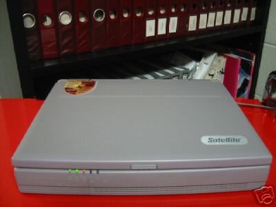
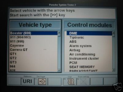
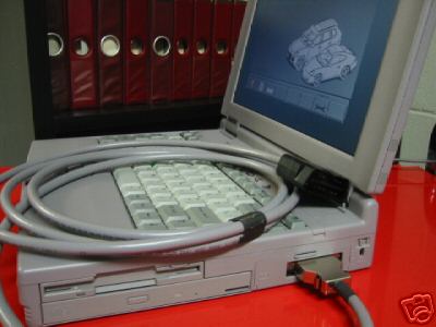
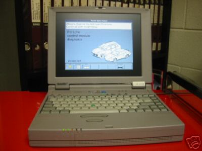
  17. The steering angle sensor (PSM cars only) is supposed to checked at each alignment - but rarely needs changing. Just so folks know... the Baum Tools Porsche Scan tool (with Porsche software module) is $3700. It looks very good but I could buy a used PST2 for that and have a lot more capability.
  18. Stock RoW Front Toe: - 1° 50' ± 30' Camber: - 30' ± 15' Rear Toe: + 10' ± 5' Camber: -1° 25' ± 15'
  19. Just added (for both US and Canada): 2006 Carrera C2 Coupe/Cabriolet (997) Order Guides 2006 Carrera C2S Coupe/Cabriolet (997) Order Guides. You can find them at: MY06 Order Guides
  20. The mirror (glass) is held in place by metal clips. If you carefully pull mirror out of the metal clips (and disconnect the electrical plug) you can inspect the clips for damage/ I think the clips are riveted in so you might have to replace the whole mechanism if one is broken.
  21. There are a couple of solutions in this thread.
  22. The tolerance color codes are different for front and rear springs and the code to use with your new springs is on the springs. A = Running gear type code, B = Compensation part code For (a Carrera) the front are: 1 white line = 3.0 mm thick compensation part 1 green line = 6.5 mm thick compensation part A = Running gear type code, B = Compensation part code For the rear: 1 white line= 0.5 mm thick compensation part 1 green line = 4.0 mm thick compensation part Your front springs running gear type for MY02 C4 Cab with RoW M030 should be: lilac/orange No blue unless you have a C4S?
×
×
  • Create New...

Important Information

We have placed cookies on your device to help make this website better. You can adjust your cookie settings, otherwise we'll assume you're okay to continue.