Welcome to RennTech.org Community, Guest
There are many great features available to you once you register at RennTech.org
You are free to view posts here, but you must log in to reply to existing posts, or to start your own new topic. Like most online communities, there are costs involved to maintain a site like this - so we encourage our members to donate. All donations go to the costs operating and maintaining this site. We prefer that guests take part in our community and we offer a lot in return to those willing to join our corner of the Porsche world. This site is 99 percent member supported (less than 1 percent comes from advertising) - so please consider an annual donation to keep this site running.
Here are some of the features available - once you register at RennTech.org
- View Classified Ads
- DIY Tutorials
- Porsche TSB Listings (limited)
- VIN Decoder
- Special Offers
-
OBD II P-Codes - Paint Codes
- Registry
- Videos System
- View Reviews
- and get rid of this welcome message
It takes just a few minutes to register, and it's FREE
Contributing Members also get these additional benefits:
(you become a Contributing Member by donating money to the operation of this site)
- No ads - advertisements are removed
- Access the Contributors Only Forum
- Contributing Members Only Downloads
- Send attachments with PMs
- All image/file storage limits are substantially increased for all Contributing Members
- Option Codes Lookup
- VIN Option Lookups (limited)
Leaderboard
-0001-0001.thumb.png.17f5bb25bf8ec261a17c21e6321c8492.png)


Popular Content
Showing content with the highest reputation since 04/01/2024 in all areas
-
It's is used at the assembly line/factory, not used by PIWIS or anything, has a data line from the DME only though that can carry the same info from DME, but no other data lines included in it like the PIWIS/OBDII connector.3 points
-
Most factory installed Zenon headlights require a separate controller for the HID system.2 points
-
Very easy task. You first have to jack the car and have it level properly. Tool needed: 10 mm allen wrench for the transmission ports. I got one mount on a socket. 17 mm socket for the front wheel drive transmission. 10mm sockets for the cover plastic nuts Very small and thin common screwdriver for the panel clips. Torque wrench. A pump for the fluid. I use a Motive Power Fill (about $85.00 with a shut-off valve) Parts needed: About 5 (1/4) liters of Mobilube PTX 75W90. I did not choose any alternate oil. I prefer to stay with Porsche and Loren recommendation! Be ready for a chock, this oil is expensive!!! Here in Montreal I could only found 20 liters container and I finally went to the dealer and he charge me $261.00 for 5 liters!!!!! And a crush washer for the transmission drain part # 900 123 118 30 ($0.52) Note : It is the only port with a sealing ring. Lets start with the front wheel drive transmission. First you have to remove the plastic cover. It is held with 6 clips and 4 plastic nuts. The best way I've found to remove those clips without damaging them is to use a small thin screwdriver and release the small clip through the opening on one side. Panel removed: Now you can see the drain port: And the fill port: Drain the fluid by opening both ports: Note: My drain port had a magnet to pickup metal chips. (There was sludge and little bit of metal shaving, normal wear to me) And reinstall the drain plug when no oil is coming out anymore: Torque is 21 ftlb for both ports. And fill through the fill port until fluid is coming out. Let it drain and when it stop you can look at the level with a mirror. It should be equal with the bottom edge of the port. About 1.5 liters is needed. Having a shut-off valve and a level indicator on the fill bottle was really useful. Reinstall the fill port and torque to 21 ftlb. And reinstall the plastic cover....Thats it for the front wheel drive transmission. The transmission is easy to reach. No panel to remove. An 10mm allen wrench is needed to remove the ports. Remove the fill and drain ports. Drain the fluid. Note: A magnet is install on the drain port and had metal but was the first oil change and suppose to be normal.... Reinstall the drain plug with a new seal part# 900 123 118 30 and torque the plug to 22 ftlb. Fill the transmission through the fill port until level comes to the bottom edge of the port. About 3 liters needed. Reinstall the fill plug (no seal needed) and torque to 22 ftlb. Hope this will help any TT owners out there! Do not hesitate to ask questions or add comments. Thanks, J.P.2 points
-
Attended an introductory high performance driving school at the National Corvette Museum Motorsports Park in my new to me 2002 996.2 C2! It was awesome! Learned a lot and had a great time. We had classes, autocross, & track time all day long. There were only 10 of us so we pretty much had an instructor to each pair all day. I learned that I am slow & can’t rev match downshift very good at all. Also learned that my stock suspension car has some body roll, understeer, & some brake feel issues. I’m thinking about some braided brake lines, good fluid, new tires, & some Ohlins suspension to start with. I have read a lot of threads about suspension, sway bars, tops, and linkages. Is there a definite go to for top mounts? I’ve been looking at the Ohlins or Tarett mounts. I want to do the coil overs first & then the sway bars. Any comments or recommendations are appreciated. The car will be used as my sunny day driver & once a month track day experience.1 point
-
Try 10761 point
-
Try 54321 point
-
Not back then - newer cars specify a bit more but the best thing is to do a factory build database check. I checked and your build code is 993330 which is a Carrera 2 wheel drive.1 point
-
Try 65841 point
-
Try 71071 point
-
Welcome to RennTech The beauty of the Porsche sports exhaust system is that if you leave the vacuum connections disconnected, it is in the loud position at all times, giving you max flow. I would simply remove the wire the previous owner installed which decreases both sound and performance and enjoy the ride.............and the sound.1 point
-
Jake has probably forgotten more than most of the rest of us combined know about these engines, so he is a trusted source. You would be wise doing both sides, the IMS, the RMS, new plug tubes, etc. all at the same time; you really don't want to go back in there six months down the road.............😉1 point
-
It is the plunger assembly in the actuator, and it is a very common problem:1 point
-
Try 50791 point
-
Had to give it another go today. Window was working fine since my last post but suddenly two days ago it started jumping up and down again, which is a pain because I just replaced the door courtesy lights. Now I have a light show in addition to the jumping window. So I replaced the interior door handle microswitch and sprayed every electrical connection except the big door latch with electrical cleaner. I then put dielectric grease in each socket and put it all back together and...still have the jumpy window and the light show. It seems like the trigger for this activity is driving over bumps and when I push on the door handle near the storage cubby. Am I right in thinking that there is a problem with the wires connecting to the back of the interior door handle?1 point
-
Try 52491 point
-
They are simply reposting what the manufacturer claims, they don't make it or stand behind it, they just sell it. For the stuff they actually make, that is another story as they do stand behind their products. At the end of the day, it is your money and your car..............1 point
-
Try 96101 point
-
Managed to get all 12 (I was mistaken on the number earlier). A few important notes for anybody attempting to tackle this. 1) USE REALLY HIGH QUALITY DRILL BITS! If a bit breaks in the head, you’re far f***ed 2) Use tons of cutting grease/fluid after every 10 seconds or so of drilling to keep bit tip cool and lubed. Make sure not to strain harden bolt going as fast as you can. Take your time and clear chips out of flutes often. 3) DRILL AS PERFECTLY STRAIGHT AS HUMANLY POSSIBLE. Can’t stress this enough. If it’s not straight you will drill the bolt and the head out. When you go to tap, you may dislodge the remaining broken bolt piece. This will cause tap to seize up and hole to be ruined. Then you’ll have to go over size with helicoil 4) You will need extended (6” long) drill bits in sizes 3/16, 1/8, 1/4 and 17/64 (or letter J 7mm). Drill but stops help too. DONT DRILL PAST THE BOLT OR YOU ARE IN THE WATER JACKET! I drilled in steps. Smallest to largest. Smallest pilot hole through center. About 20mm of thread engagement to drill through and a 3mm air gap in between end of bolt and head so when you get through you’ll feel it. Don’t keep going! 5) You will have to remove the thermostat and drain the coolant in order to be able to drill that last one on drivers side straight on. The thermostat housing eclipses the bolt by like 1/4”. Also, undoing the mounting for the coolant tube helped make room for drill head. 6) Stainless hardware or very high grade hardware and nickel anti-seize will last forever. I also used a torch and an air hammer to heat up and remove all 6 manifold collector studs and replaced with grade 10.9 bolts and nuts. 7) Have a face shield and long sleeves because it will be raining hot molten metal chips down in your face for 3 days straight 8 If you have the funds I highly suggest stromski racings drill guide kit but it is pricey for a one time use item 9) when tapping use grease, check x and y to make sure you’re staying straight, remove and clear chips out of flutes often and use the 3 turns forward 1/2 turn back method 10) vacuum fill the cooling system or fight bleeding1 point
-
Follow the wires from the light and fan down the deck lid to the right side of the engine compartment. You will find a connector there (X23) - disconnect it and make sure the pins are good and clean.1 point
-
Try 98421 point
-
If memory serves, there is an extraction tool for exactly this purpose, but I do not have a link for it. Maybe listed as a VW tool.1 point
-
Try 43151 point
-
Fault code 1772 Pressure sensor signal wire Possible cause of fault - Short circuit to B+ in the wiring of pin 84 of the level control module - Short circuit to ground in the wiring of pin 84 of the level control module - Open circuit in the wiring of pin 84 of the level control module - Level control module receives implausible signal from pressure sensor - Pressure sensor faulty - Level control module faulty
 1 point
 -
Try 12871 point
-
Try 53801 point
-
Try 46251 point
-
If your car is MY2003 and later then it is a MOST bus car, i.e., the audio units, radio, CD, amps, communicate with each other using fiber optics. That box is a MOST bus interface for the PCCM+ to be able to communicate with the amps. All MY2003+ cars need that box.1 point
-
I just solved my 4 wheel error code. The problem started when the battery was nearing end of life. After replacing the battery we still had the issue. Next replaced the servo & then ECU to no avail. Next we upgraded the battery from Interstate to OEM but that didn't work. Porsche of Stevens Creek was of no help so I searched the web & found this at Pelican Parts and found a procedure to basically sync the system IT WORKED! Sorry, I cannot find the link but I did summarize it in a text. 1. Activate off-road /Low Range mode/ driving program (use rocker switch) with gear shift lever in neutral position 2. Drive your car for a while (move forward/backward several meters) 3. Activate on-road /High Range mode/ driving program (use rocker switch) with gear shift lever in neutral position It may "heal" your all-wheel drive system, e.g. resistor, which identifes mode in which system is and generates fault message when corroded - it happens when you do not use this feature for a long time... I did this and drove around the block. It's been a month and the error code has not returned. We bought the vehicle in 2017 and never once adjusted the range. I'd wager the first time it had ever been adjusted is when I followed the procedure.1 point
-
We have installed many B&M shifters over the years, and they have proven to be one of the best when it comes to durability, and in fact we have never had to replace one. More likely, you have a cable or cable end issue.1 point
-
"I did see a message at one time while cranking saying the immobilizer was not in a ready state but I haven't been able to reproduce that message again." That is very concerning, that unit will paralyze the car if it is unhappy, so I would start there, pulling the unit and looking for evidence of corrosion, water damage, and check the glass fuse in the unit itself.1 point
-
I think it is more the other way around; K40 are well known for their "hidden" systems that range from radar and/or laser detection systems, as well as highly illegal jammers to block both radar and laser signals. Even their very basic systems start at around $700 for their portable units, so they are rather expensive to say the least. I have never been a fan of their hidden systems as they tend to mount the signal receivers low to the ground (in the front grill or near the rear license plate for example) which dramatically reduces their effective range. To offset this limitation, K40 turned up the wick on signal sensitivity, which tends to lead to constant false signals, as you just found out 😉1 point
-
I have the pleasure of dealing with suspension problems on my 2011 Cayenne turbo. I learned a lot about this system through trial and error. I will give you the highlights of what I know.... When it will not inflate it is obviously due to lack of pressure. This system uses nitrogen. If you fill with nitrogen it will fix your problem at least for a little while. You probably have a leak somewhere and it has caused the compressor to go bad. I borrowed a friends nitrogen bottle and purchased some parts from Porsche and snap on and bought an adaptor from a hydraulic shop and used an AUTEL scanner (pro grade that will calibrate suspension) to do a fill. After filling I sprayed the struts one at a time to figure out where my leak was. I had a leaky left front strut. I replaced both front struts and the compressor and filled with nitrogen and the car has been good for about 2 years. A Porsche expert diagnosed the car for me as just needing the compressor and he was happy to replace for about $4000. I said no thank you and fixed myself after paying for his diagnosis which was only partially correct. I hope this helps.1 point
-
Thanks for the help. Well, my mechanic downloaded a set of "european cars drivers" for his scanner, deleted the fault and everything went good, so now the tiptronic works flawlessly. Thanks.1 point
-
This tutorial shows steps for replacing air filter on Panamera. Does not look hard, but to get full instructions/steps, please watch other turorials in the following order: 1. Panamera headlight removal 2. Panamera front bumper removal 3. This tutorial - Panamera air filter replacement Hope it helps out. DIY you get to make sure things are right every time.1 point
-
While looking for a good garage door opening solution for my MY01 996 C4, I came across some posts referring to the Gentex auto-dimming mirror with Homelink. Some posts suggested that there was a VW/Audi adapter that would allow this universal fit mirror to be installed on a 996 windshield. Other posts suggested that it was easy to tap into the existing dome light and sunroof switch wiring. So I decided to give it a go. It was a relatively easy install, and one of my best mods yet. Step 1: I purchased the Gentex GENK40A Auto-Dimming Mirror with Homelink on Amazon (American Security Company) for $249. My kit came with a VW/Audi adapter and a free wire cover. Here is the mirror, the piece of the wiring harness that I used (it came with a full, route to fuse box wiring), and the wedge adapter. Here is a close-up of the adapter. Here is the wire cover. Step 2: Remove the old school mirror by rotating the base 90 degrees counter-clockwise. I put masking tape around the base and used channel locks and a firm grip to rotate the base 45 degrees. I continued rotating the base by hand another 45 degrees until it released. Be careful as you don’t want to break the windshield -- been there, done that on a wiper blade DIY, oops! Step 3: Slide the adapter onto the windshield button cam and secure with hex key set screw. Note that my adapter did not fit out of the box. I used a small file to remove material around the inside of the adaptor until it fit snugly around the button cam. Since the adapter is aluminum, this was easy work for a steel file. I also primed and painted my adapter matte black to make it more inconspicuous. Step 4: Plug the wiring harness into the rear of the mirror, and remove the large red harness at the other end. The color coding for the wires is as follows: (1) Red = switched power; (2) Yellow = un-switched power; (3) Black = ground; and (4) the two Green wires are not used for this mirror (they are used for other Gentex mirrors with temperature displays). Step 5: Mark the outer wire casing so that you can split it for purposes of routing the wires through the mirror base. Don’t forget to leave some slack for mirror adjustment. Step 6: Slide the mirror base over the adaptor. Tighten the mirror base set screw with a T20 Torx driver. Step 7: Now it’s time to remove the dome light / sunroof switch housing. First, remove the two black alien eyes with a plastic trim tool. Next, remove the two screws underneath the alien eyes. Then, carefully pull the end closest to the sunroof away from the headliner until the rear tabs release. To fully release the housing push it towards the windshield so the front tabs release from the mounting edge. You’ll understand when you are in there. Step 8: Identify the existing wires that you need to tap into. After testing with a test light, I used the following wires: (1) the Red/Green wire with black spots going to the sunroof switch for switched power; (2) the Red/Black wire going to the dome light circuit board for un-switched power; and the Brown wire going to the dome light circuit board for ground. Step 9: Install the wire cover by clipping it into the top of the mirror base, and route the wires from the mirror through the cover and into the dome light housing. Note the wire cover that came with my kit was way too long, so I cut it down to size. I also made a channel out of mine to cover the wire on the inside. The inside cover was cut a little shorter than the outside piece to make it easy to route the wires. The dome housing will fit over the wire cover, so thankfully there is no need to cut a whole in the housing. To make the install look cleaner from the outside, I intend to go back and use a thin strip of black film on the inside of the windshield to better hide the wire cover from the outside. You might want to try this now. Step 10: Now it’s time to make the connections. I used 22-18 gauge splice tap connectors. The connections are as follows: (1) Red to Red/Green with black spots; (2) Yellow to Red/Black; and (3) Black to Brown. I wrapped up the unused green wires with electric tape. Step 11: Reinstall the dome light / sunroof switch housing by: (1) pulling the front tabs onto the mounting edge; (2) snapping the rear tabs back into the headliner (you may need to move the wires around a bit to get a good fit); (3) replacing the screws under the alien eyes; and (4) replacing the alien eyes. Step 12: Test the install. The Homelink buttons should work when the ignition is off. Press each and you should see a red light come on. With the ignition off, the anti-dimming feature should be off. If you press the 1 button, nothing should happen. With the ignition on, you should see a green light indicating that the anti-dimming feature is on. You may need to press the 1 button the first time. It should go on and off with the ignition after that. You can verify that it is working by covering the sensor on the back of the mirror and shining a light on the sensor on the front of the mirror. I found that the mirror works really well in real life conditions. Step 13: Program the Homelink buttons with the included instructions. Step 14: Congratulations, you are done.1 point
-
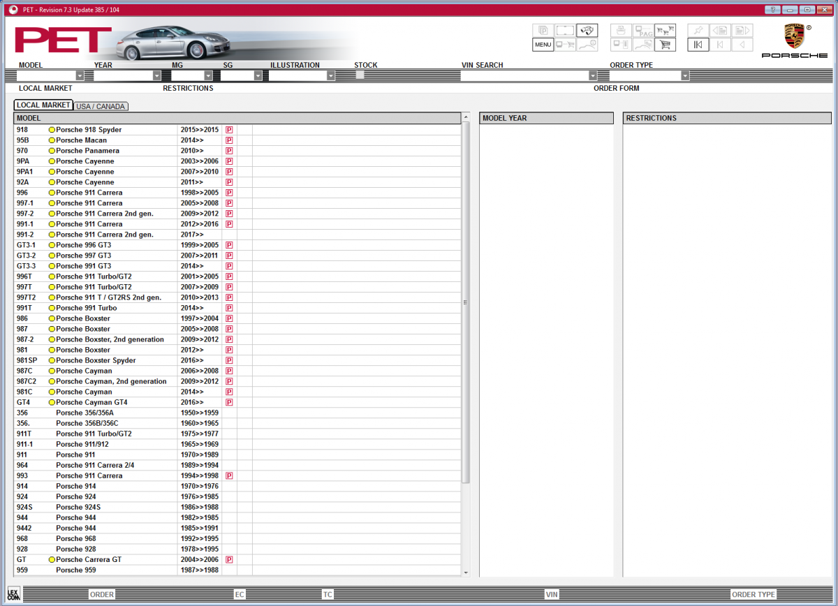
With all due respect you are mistaken. We use the same model numbering/labeling that Porsche uses in ALL their documentation. (click to enlarge)
1 point
-
Flange center bolt's nut is 13mm. (I suspect it has been touched because the other three bolts on the flange are "indented" 6 point torx, not traditional hex bolts like some of the other bolts on my images.) Once again, much appreciated, excellent answer JFP, :notworthy: OK, with a 13MM center bolt nut you still have a removable IMS bearing (the non serviceable unit is the only one using a 22MM nut). The flange bolts are the correct single use microencapsulated units, you should have new ones with the IMS kit.1 point
-
Hey great DYI. Can you tell me how you got the beauty ring to move? Mines in the 1 o'clock too. Thanks.1 point
-
On occasion during the most humid months of the year, the air coming out of the vents of my nearly 8-year-old car would smell a little 'off.' Since the a/c condensation was draining just fine and the odor wasn't ever-present, it wasn't a major concern to me. However, surfing the web I found a variety of A/C refresh kits that seemed worth a try, if for no reason other than to experiment and see if it was any benefit. But, no good deed goes unpunished. There are a variety of kits out there, some seem OE but most are aftermarket. I found them to have so much in common that I began to think they were made by only one or two manufacturers. The kits I was considering are two products: 1) a foaming spray that you inject into the evaporator housing through the condensation drain, and 2) a spray that you empty into the external air intake while changing the HVAC settings. The kits state or imply that they will clean the evaporator of crud that comes from dirt, mold, mildew, etc. and kill whatever causes odors in the venting. As I mentioned, the kits seemed nearly identical to each other so I bought one based on convenience at a local parts supplier for about $18. For another point of reference, there is a Toyota kit, part number 00289-ACRKT, that you can find here for instance. The product I used was the following: Note: This attempt to clean an HVAC system was for my particular 2003 986S. Other vehicles may be different and there are safety risks involved in doing mechanical or electrical work on a vehicle. What's presented here is a general overview of my DIY project, not a complete step-by-step set of instructions. Please obtain, understand, and follow the necessary repair and installation procedures in order to work safely, avoid damaging anything, and achieve a safe result. Preparation steps: I raised the vehicle up onto four(4) jack stands. Then I loosened or removed numerous underbody panels to expose the area under the passenger side floor pan. The location of the condensation drain is identified by an arrow in the photo below: First use the larger can of "evaporator foaming cleaner." You can read the instructions on the can in one of the photos above. I had to use another piece of tubing between the tapered nozzle and the condensation drain because the drain tube is not flexible and wouldn't hold the nozzle. That should have been the first indication to stop. Notice the grommet around the drain tube in the photo above and how the tube is inconveniently situated between the hot water supply/return for the heater core. As I was trying to force the tubing onto the drain, I pushed the drain tube and grommet into the passenger compartment. I knew it was going to be a pain to put it back, and it was. I had to remove the umbrella trim along the passenger-side door threshold, loosen the floor carpeting, and shove my arm under the carpet to reinstall it. Photos of the attachment and foam injection below: The foam went in, it seemed to sit for a while, it liquefied a bit, and then it drained out. The photo below was taken at a moment just as it was starting to drain: The liquid in the bucket was mostly clear, with a little particulate matter--nothing worth photographing. It didn't have much of a smell; it was slightly medicinal, like disinfectant. Following the instructions on the can, the next step is to use the "a/c intake refresher." Take out the pollen filter and spray into the air intake. You are supposed to change the vent settings between spraying intervals so that the mist runs through different duct work. Again, it has a slight disinfectant smell--pleasant but not flowery and not too strong. Not too bad, right?... Well, I was too preoccupied with the camera to realize what was happening inside the car: After all the effort for something that wasn't really necessary… I had to laugh. I was doing this process as I was preparing the car for winter storage. It was about 40° F (4° C) in my garage. Obviously, a lot of the foam didn't liquefy and drain. If I were to do this again, I would warm up the HVAC system beforehand, or just do the whole process at a higher ambient temperature. I'd also let the evaporator core drain longer (a lot longer) before doing the 2nd can. The photos above are the worst of it; only a little came out of the other vents. I blasted the system for a long time after that and it cleaned up without a problem--no damage to any surfaces. A few days ago I fired up the car for the season. No issues. Live and learn and pass it on. --Brian1 point
-
RFM is right on the money. The most common cause for this is a leaking drivers side fuel tank flange. Should be part # 955 620 841 00. Due to the design of the tank, both flanges must be removed( there is one on each side of the tank) so you'll also want two sealing rings ( 955 201 133 01) There is an updated pipe that porsche wants you to install on the drivers side flange as well, 955 620 911 001.1 point
-
Please recommend a low profile, light weight, easily stored - floor jack. Thank you1 point
-
Here is how you replace the spring in the center console on a 2006 997S. The cost of the part was 87 cents. Here is a picture of the part. You remove eight torx screws to get the cover off. This is the cover off. Here is the cover. There were two different length screws but it does not matter where they go. Next you release tension on the spring. I have a torx socket resting on the spring release. The last step is to pull the hinge pin out. I used a vice grip and it worked real nice. Replace the spring and reassemble. This is a very easy task with a difficulty index of 1. I replaced the spring because the console door would rattle over bumps. The new spring works like a champ. Paul1 point
-
The symptoms for this include CEL and Long Cranking times when starting after filling up. Part Required 948 110 202 01 (75 from dealer, 45 from Sunset) Some new Twist locks for the trim panels, since they have a mind of their own. You will need to remove the throttle design cover pull up it comes right off. then you will need to remove the 4 t 30 torx screws on the drivers side coil cover. then that cover will pull up although it is a pain, you can wiggle it out. Use a large flat blade screw driver or a penny to remove the 1/4 twist locks that hold down the drivers side engine compartment cover (the big black one) there should be 4 1/4 ttwists Then remove the rearblack panel, 1 1/4 twist in the center and 2 on the pass side of it. Remove the panel the purge valve is in the front of the engine between the head and the intake on the drivers side. It looks like a black cylinder little bit bigger then a film canister with a hose on one end to the front and the back is a hard black plastic line that runs along the intake and comes up in the back and goes to a rubber hose on the fire wall. Un plug the valve and push it off its bracket, undo the clamp with a pair of plairs and pull the hose off (sometimes you need gently grab the hose with the pliars and twist to loosen it up from the valve, you can damage the valve just not the hose). In the rear you will need to do the same, the rear hose never comes off easy I think they glue it on, use you pliers to crush the plastic line where the hose is over it. once it is crushed enough it will come off with needle nose pliers. Undo the injector electrical connections (wire clip on each) and pull them off, also free the ratcheting clip on the 1 inch flexy pipe crossing over the top. These 2 steps make removing the pipe a lot less violent. I did not and I would do the next time (hope not) I would cut the pipe after you have sprung it out of the gold clips along the intake, it make it easier to remove The pipe has some sleeving which is re-used, see when they are before you remove and put them back the same The hard part is the removal, putting it back is a piece of cake., Dont forget to hook a durametric to clear the code. I filled up for the first time this morning, perfect start afterwards. I need to give credit for this to a certain dealer tech from Miami (Firehawk) without whose help I would not have been brave enough to do this myself.1 point
-
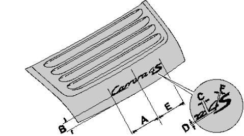
997 1. Find the middle of the lid. 2. Position logo Carrera with the dimensions A and C Carrera logo dimension 129.6 mm+/−1 mm and B Carrera logo dimension 45 mm−1 mm and stick on lid. 997S 1. Find the middle of the lid. 2. Position logo Carrera with the dimensions A Carrera S logo dimension 175.6 mm+/−1 mm and B Carrera S logo distance 45 mm−1 mm and stick on lid. 3. Position logo S with the dimensions C Carrera S logo dimension 175.6 mm+/−1 mm and D Carrera S logo distance 39 mm+/−1 mm and stick on rear lid. 9974S 1. Find the middle of the lid. 2. Position logo Carrera with the dimensions A Dimension: 175.6 mm +/-1 mm and B distance: 45 mm -1 mm and stick on lid. 3. Position logo 4 with the dimensions C Dimension: 19 mm +/-1 mm and D Dimension: 2 mm +/-1 mm and stick on rear lid. 4. Position logo S with the dimensions E Dimension: 190 mm +/-1 mm and F Dimension: 3 mm and stick on rear lid.
1 point
-
If your battery is dead and you need to get into the front trunk, it may be necessary to locate the manual pull wire to open the front trunk and get to the battery. This might be more difficult to locate the first time. You may not be in a good location to wrestle the right front tire splash guard to find it. It might be night time or you may not be dressed in the correct clothes to be down by the tires trying to locate it. I would recommend that you take the time to locate it in good weather and in the comfort of your garage or better yet re-route the wire to the front bumper behind the plastic plug the hides the location for the tow fish eye bolt. To get started I removed the carpet liner in the front trunk. The front trunk liner is made up of 2 sections and I only had to remove the front section. There was one thumbscrew clip on the passenger side and one thumbscrew clip opposite on the driver's side. Also on the driver's side there was one snapin clip and 2 additional snapin clips located in the front of the trunk. All five clips are very easy to find and remove. I then removed the plastic trim directly on top of the front trunk latch and microswitch. There are 4 screw plugs and you simply turn the plastic plugs 1/4 to 1/2 of a turn: I then removed the passenger side head lamp by using the tool in the Boxster tool kit. The kit is usually located near the spare tire in the front trunk. Turn the wrentch about 1/2 turn counter clockwise to unlock the headlamp. Slide the head lamp out. You may have to jiggle it a little but it should slide out with very little effort. Once the light is out you will be able to locate the pull wire. It is clamped into a lasso at the end. In the photo below you can see it at the end of the red arrow. The red oval in the top of the photo is the plastic wheel splash guard. The passenger front tire is directly behind that. Some recommend to access the pull wire from the tire side but that is a little more difficult and you still have the problem of trying to re-rout the wire up to the front bumber. Doing it from the head lamp side makes it easy. Here is another photo with my finger pointing at the pull wire. Remove the front bumper plastic cover that hides the tow plug. I used a plastic upholstery tool and the plastic cap popped right out. The plug has a fishline wire connected to it to prevent you from losing it. Use the light from a flashlight to guide you (from the front bumber side) and re-route the pull wire from the headlight to the tow plug. Having the top plastic guard off makes this very easy. Tuck the pull wire back in and re-insert the pastic bumber plug. Reassembly is just the reverse. Slide the headlamp back into the guides and push it home, use the wrentch and turn clock wise. you will hear a loud pop when the headlamp is secured. You know have easy access to the emergency pull wire.1 point
-
1.) Un-screw the one phillips head screw at top center of side air intake... 2.) The molded air duct and the intake grill are still attached by three delicate plastic tabs at the three points... The best way to remove this is gently insert your fingers through the grills into the intake at the points circled in red and gently try to free the tabs... All three points come forward towards you, but if one is stuck or gets caught it will break... 3.) Inside the drivers side air duct you will find a snorkle... The snorkle is added to most US cars for noise restrictions. Now this piece is attached by no screws or tabs, but it most likely will give you some troubles removing... The best way is to remove this, just grab a hold of the long snorkle (not the small dish on the end)... Now wiggle it from left to right and vice versa while pulling out towards you. This works, but might take a little effort. 4.) This is what the intake is going to look like after the snorkel is removed... Just carefully insert the three tabs back into their points... Make sure that all three are tightly in by pushing the airduct cover (not the grill)... Insert your 1 screw into top center of cover and you are done.1 point
-
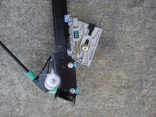
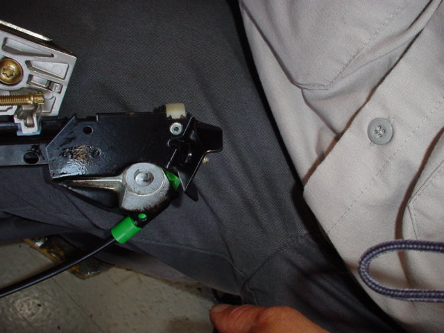
Replacement regulators use to come with 2 stops installed that were blue plastic and were held in place with a torx screw. You left in the upper stop for a Boxster. The new replacement regulators I have seen come with the lower stop riveted in place. The upper stop and rivet is in a plastic bag. Those stops are white plastic. Did not ask the mechanic why the window travel is different on 986/996. At least that is what I remember.
1 point
-
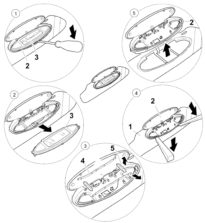
Because of the demand for disassembling sun visor - here it is: 1. Unclip mirror insert 3 -- Insert a narrow screwdriver between the mirror insert 3 and the mirror housing 2 at the bottom center, and unclip the mirror insert. 2. Remove mirror insert 3 -- Pull the mirror insert 3 upwards and remove from the mirror housing 2. 3. Remove bulb 5 and contact clips 4 -- Remove the 12V /3W bulb 5 from the contact clip 4. Take the contact clips upwards out of the holder. 4. Unclip mirror housing 2 -- Insert a narrow plastic spatula between the mirror housing 2 and the sun visor 1 on the left and right and unclip the mirror housing. 5. Remove mirror housing -- Take the electric lead out of the mirror housing 2 and detach the mirror housing from the sun visor.
1 point
-
Note: Part numbers sometimes change without notice. Always double check with your supplier that you have the latest part numbers. The switch is part number 996.613.155.00 A02 for a switch installed on the left side of the dash and 996.613.156.10.A05 for a switch installed on the right side of the dash. Like other dash switches it has a raised portion on one side. When you order the switch, ensure you specify which side you want the raised portion according to which side of the dash you are installing it into. These install procedures assume you will be placing the switch in the unused dash socket below the PSM switch on a RHD car. For LHD cars, the PSM switch is on the left side of the dash and the raised portion of the tail switch should also be on the left (as shown in the picture). For RHD cars, the PSM switch is on the right of the dash and the raised portion of the tail switch should also be on the right. Take care that you order the correct tail switch for your car. Parts you will need: 1 ea 996.613.155.00 A02 (or 996.613.156.10.A05) Spoiler Switch 5 ea Female connectors 5 feet (1 length) Connector cable 2 (3 inch length each) 14 gauge wire few Cable ties Tools you will need: Phillips head screw driver Blunt flat blade to prise the switch tab (I used a butter knife) Wire cutters Crimping tool Soldering iron Remove the cover from the fuse box. Then carefully remove the four screws pointed out in the picture. Ensure the screws do not fall into the fuses else you may start a fire! (The fusebox is located in the drivers side footwell.) Once the screws are removed, pull away the carpet trim around the fuse box. You will be cutting into the wiring loom connected to the existing spoiler (tail) switch. The switch is the black square item located in the bottom left corner of the fuse box. Note: The installation of the new in-dash tail switch does not effect operation of the existing spoiler (tail) switch. It is simply wired in parallel to it. I have used a mirror here to show you the back of the fuse box. Pull the connector from the switch. It has no clips but it may be quite hard to pull off. Be careful not to pull the wires out of the connector. DO NOT use a metal implement to pry it off. If you rock it from side to side while pulling, it will eventually come off the switch. Here you can see the connector pulled away from the switch. The connector has three wires: Green/black, Brown/Green and Brown. Carefully cut the 3 wires going to the connector. Ensure you do not short the wires as you cut them. Leave a long tail on the wires at the connector as you will need to splice them back later Use a blunt blade to carefully pry out the switch tab holding the PSM switch in the dash. I used alarm wire in a single cable. You need 3 cores in the cable and it needs to be about 5 feet long. Feed it through the opening for the PSM switch tab. You can see in the picture where you can feed it through the back. Push the wire through so that you can grab it from underneath the dash and feed it along within the dash to bring it out behind the fuse box. Carefully cut the 3 wires going to the connector. Ensure you do not short the wires as you cut them. Leave a long tail on the wires at the connector as you will need to splice them back later Fit the new tail switch into an unused slot. Usually the one below the PSM. Place the connectors as shown on the switch. Make a note of the colour coding you use and which switch terminals you put them on. I used red, brown and black wires in this configuration. Next you will wire up the tail switch light. Use two 14 gauge wires cut to about 3 inches. I used blue and brown wires. Strip both ends of the two wires. Crimp a female tag onto one end of each wire. Connect the tags on these wires to the two outer (remaining) tail switch tags. Pull off the connector from the back of the PSM switch. Insert the blue wire onto the left most PSM switch tag (blue/pink/brown connection wire). Insert the brown wire onto the top PSM switch tag (red/blue connection wire). Ensure the inserted wires are not shorting any other tags. Push the PSM connector back into place with the inserted wires. One way to do this is to cut the bare ended wires short and feed them through the tag holes before pushing the connector back on to the PSM switch. At the switch box end, feed a 1 inch piece of heat shrink sleeve onto each of the 3 exposed loom wires. Push the sleeves along to expose the bare wires. Pre-solder each end on all exposed 9 wire ends. Then solder the loom wires back together while at the same time splicing the new wires into the loom. The 9 wires comprise 3 from the original Spoiler (tail) switch connector, 3 in the loom that you cut from the tail connector and 3 that you have just wired in from your new tail switch. The wires are soldered as follows: red -> red/green black -> green/black brown -> brown Check the solder joints. Push the sleeving over the joints and use the soldering iron to heat the sleeving so that it shrinks around the solder joints. Ensure no strands of wires or solder is protruding from the sleeving. Refit the connector back to the original fuse box spoiler (tail) switch. It is important to tidy up your cabling. I used cable ties to ensure the cables don't rub on anything sharp. Before refitting the switch tab, test that your newly installed in-dash tail switch works. Also test that the switch light works when you turn your side lamps on (with ignition on of course). Finally, replace the switch tab in the dash, push the fuse box surround carpet back into place and replace the 4 screws. Job done.1 point
-
There is no such thing as lifetime antifreeze. The fluid may last a lifetime, but not the **** in the coolin. system. Changing it every 3 years of so is highly recommended to flush out al the crap.1 point