Welcome to RennTech.org Community, Guest
There are many great features available to you once you register at RennTech.org
You are free to view posts here, but you must log in to reply to existing posts, or to start your own new topic. Like most online communities, there are costs involved to maintain a site like this - so we encourage our members to donate. All donations go to the costs operating and maintaining this site. We prefer that guests take part in our community and we offer a lot in return to those willing to join our corner of the Porsche world. This site is 99 percent member supported (less than 1 percent comes from advertising) - so please consider an annual donation to keep this site running.
Here are some of the features available - once you register at RennTech.org
- View Classified Ads
- DIY Tutorials
- Porsche TSB Listings (limited)
- VIN Decoder
- Special Offers
-
OBD II P-Codes - Paint Codes
- Registry
- Videos System
- View Reviews
- and get rid of this welcome message
It takes just a few minutes to register, and it's FREE
Contributing Members also get these additional benefits:
(you become a Contributing Member by donating money to the operation of this site)
- No ads - advertisements are removed
- Access the Contributors Only Forum
- Contributing Members Only Downloads
- Send attachments with PMs
- All image/file storage limits are substantially increased for all Contributing Members
- Option Codes Lookup
- VIN Option Lookups (limited)
Leaderboard
-0001-0001.thumb.png.17f5bb25bf8ec261a17c21e6321c8492.png)

Popular Content
Showing content with the highest reputation since 06/04/2010 in all areas
-
Does anybody has this problem with their horns? Basically, if I go over a bump, or stop on a slope, the horn will turn on. It is very annoying especially people in front of you thought your are hornking at them. Any advise, will be helpful. Thanks, -Nat31 points
-
This is a continuation from the front wheel bearing change. That was good practice for the rear of your car. Although i thought the rear was more difficult than the front but after i was done and found a couple of tricks that i will share, it might actually be easier. Having the right tools always make things go smoother. The B90-P2 tool i bought at http://www.samstagsales.com/Porsche.htm#axle Took only 3 days to get it. I was away at work for 4 days so the timing was perfect. Great service. Earlier this year people were wondering where to get the tools to take apart the electrical connectors. Well sams tag sales has all the Porsche tools needed. With the SIR TOOLS kit they sent me the catalog with all the speciality stuff. If you don't have an arsenal of basic tools i would recommend going to Sears. The prices are higher than a China Freight but Sears does treat their people well and nothing like supporting the american people right? Attached is a photo of a great tool set that has almost all that you need. It even comes with the 32mm large socket for the hub bolt. Aside from those tools you will need some larger wrenches. 21mm for the track arm. (Actually you don't have to take this apart...more later) But you do need some larger wrenches for the Sir Tools Kit. 1 and 1/16. Some allen key sockets. Best to get a set of 7 in metric. Sears also sells the Torx socket set too. You will need at least 2 torque wrenches. My trick for the 360 foot pound setting is later. Some plyers, punch, screwdriver set. Phillops, flat etc... Discount auto parts sells a paint can full of GunK degreaser. And has a tin to put the small bolts in. Great stuff. Don't drink it. If i forgot some i will post it further down. So lets get going... Have the car parked so you have lots of space to work around it. Back the car into the garage far enough so you have room to close the garage door if you need to make a run to the tool store. Don't ask me why i mention this! Set the parking brake, and remove the center cap. I pushed in an allen key and used a vice grip to pull it out. Pull hard. Get your long 4 foot bar, 32mm socket and loosen the axel bolt. You can even take it off all the way, it doesn't reall matter. Loosen the 5 lug bolts, 4 19mm and the third i hope you have the locking one. Jack the car up and put it up on stands. You will need to use the jack later and it just isn't safe to have your head under a car with just a hydraulic jack. Remove the wheel bolts and then the wheel, don't forget to use the factory supplied tool to help with the removal and installation of the wheel.30 points
-
Finally got around to doing the front wheel bearings on my 1999 Boxster. I bought the SIR Tools B-90 P2 kit. $259.00 Bearing seperator from China Freight $29.99 (ON Sale) Craftsman 32mm large socket. $11.99 4 foot bar extension or pipe. (Home Depot $10) Bearings from, I can't remember but a while back. $30ea Jack Stands Jack Important Anti Seize Compound $8.99 (NAPA) Large wrench set. Sears $59.99 (I kinda went overboard on the wrenches. They had them on sale and even thought Craftsman is a lot more than China freight they treat their employees well, i think they are made in the USA and we need to support American companies, my .o2) Various other tools sockets, punch, spring compressor etc...You will see as i go along. So first off is to open the front trunk and get out two tools. The wheel lock key and the wheel post. Start off with taking the center cap off the wheel while it is still on the ground. Take the 32 mm socket and loosen the big center bolt. You will need to use a large ratchet, small extension and stick the home depot bar on the end. Be careful to use a quality ratchet or it might break and you will be doing some paint work later. I had taken the steel bar and pounded it into an oval shape so it would fit overtop of the ratchet. This bolt is tight so make sure you have the parking brake on. Next loosen the wheel bolts and jack the car up. Take out one bolt then put the alloy peg in one of the holes. This helps line everything up and keep the wheel from falling onto your nice painted caliper. You should have the wheel off and put somewhere out of the way...You won't be needing that anymore...At least for a while. On the front of the rotor there are two phillops screws. I like to remove them now as the brake pads are holding the rotor from spinning. You may need a special tool to get these out if they are stuck. Just be careful not to strip them.28 points
-
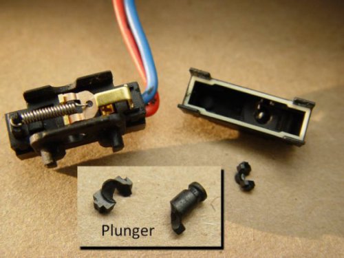 It seems that there are more and more cases of these faults appearing, and as some of our cars are reaching 10-12 years old, it is hardly surprising. I've compiled this information from past personal experience on both of my 996s, reading about others on here and other forums, referring to the workshop manual and wiring diagrams, and applying some logic. Hopefully you might find it useful, and save some grief when troubleshooting. DOOR MICROSWITCHES There are seven microswitches in each door which control the alarm system. Two are separate switches: a] One on the outside door handle. This switch is used to sense that the handle is lifted. b] One on the inside door handle, which has the same function. When the car is unlocked and either handle is lifted, this signals the alarm control module (ACM) to lower the appropriate window by 10mm, and turn on the interior lights. As soon as the door opens, another switch inside the door lock (explained later) tells the ACM that the door is open, which holds the window down until the door is closed, when the window is raised, and the dimming timer on the interior lights is started. Once the car is locked, the outside handle switches are ignored by the ACM. The remaining five switches are inside the door lock assembly: c] One switch senses if the door is open or closed. d] One senses that the key has been turned to the 'lock' position. e] Another senses that the key has been turned to the 'unlock' position. f] One senses that the door lock motor has reached the 'lock' position. g] Another senses that the door lock motor has reached the 'unlock' position. TYPICAL FAULTS All these microswitches can be problematic, and it is common for one or more to fail at some time. These are some of the common failures and symptoms: 1) The door window won't drop when lifting a handle. This is usually the handle microswitch which has failed. 2) The window drops, but goes back up when the door opens, or when the handle is released. This can be the handle microswitch, or more likely the 'door open/closed microswitch' ( c ) has stuck. Because the system thinks the door is still closed, it sends the window back up. 3) Door window won't go up the last 10mm. This is likely to be the 'door open/closed microswitch' ( c ) stuck in the opposite sense to (2). The system thinks the door is still open, so won't allow the window to go back up. Note that in this case the door will still lock, but you may get a single-beep from the alarm horn. 4) Door will not lock with key. The 'key lock' microswitch (d) is broken. This is very rare, as this microswitch is hardly ever used – most times the car is locked by remote. 5) Door will not unlock with key. The 'key lock' microswitch (e) is broken. This is also very rare, for the same reason. 6) Door locks, and then immediately unlocks, usually accompanied by a double-beep from the alarm horn. This is the 'door locked' microswitch (f). The locking motor physically operates the door lock, but the microswitch to sense this has failed/stuck. The ACM promptly unlocks the car. In this case, the only way to lock the door is to use the emergency locking procedure. Turn the key in the door to the lock position and back three times in quick succession. 7) The door unlocks, but there is a beep or double-beep from the alarm horn. This is the 'door unlocked' microswitch (g). Although the door is unlocked, the ACM has not recognised that. The alarm will not sound, as turning the key in the lock has deactivated it. FIXES The inside and outside handle microswitches are available separately, and are not too expensive. Although alternative equivalent switches may be available, the genuine Porsche switch comes with a connector and wiring, so it makes sense to use an original. Part Numbers: Inside handle microswitch: 996.613.123.00 (Same both sides) Outside handle microswitch: 996.613.125.00 (Left) / 996.613.126.00 (Right) The door lock microswitches are not available separately. You have to buy the complete door lock assembly, at a cost of around $120. It has been known for people to repair the offending switch though. This is a picture of a typical failure of a 'door open/close' microswitch (courtesy of another RennTech member): You can see that the plastic plunger has broken, jamming the switch lever inside. These switches are (apparently) made by Burgess, but as yet the source and part number are unknown. There are several other similar standard switches on the market for around $2, and people have stripped down the new switch and rebuilt the old one with the plunger from the new one. OTHER SWITCHES IN THE ALARM SYSTEM The other switches and contacts in the alarm system are to monitor the lid closures: Front lid microswitch Rear lid microswitch Oddment compartment microswitch Glove box microswitch Radio contact (to detect radio theft) An open compartment or switch failure will cause a single-beep of the alarm horn on locking. A system error will cause a double-beep. Other elements of the system include an interior monitoring sensor (in the overhead lighting), an alarm readiness light (on the dashboard in the centre) and a central locking button (on the dashboard). Options are a tilt sensor (next to the battery or under the left-hand seat) and an alarm siren (next to the battery).27 points
 -
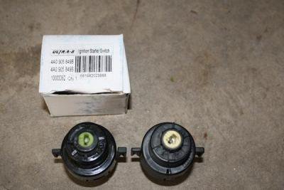 First off - thanks to everyone who has been down this road before me for providing tips and suggestions and troubleshooting regarding this common problem. I have been dealing with a key that would stay all the way to the right upon starting meaning that the A/C, heated seats and some other items would not function. My solution had been to simply start the car and then just move the key back one notch to the left and everything worked fine. So if others have that issue, my original solution will work but obviously the problem remains and at some point you may end up stranded if the ignition switch completely fails. I stumbled upon some of the other threads and found that this needed fixing and I opted to replace just the switch as opposed to upgrading to the new complete unit that Porsche has moved to. This procedure is not new to the board, but I thought a step by step with pictures may be useful to those looking for an inexpensive solution. It cost me $12.11 including tax. If your ignition mechanism has been changed to the newer revised unit the ignition switch is a different part number but I assume the steps would be the same. The part for just the switch - no longer available through Porsche since they are only selling the entire $150 unit - is 4A0905849B. The switch alone is available mail order through Pelican for $10, Autohausaz.com was +/- $8.75, Ebay has them all over the map from $15-30. All of these options will work but require shipping charges and delivery time. I was hoping for a local option since I had the time to do it today. Here is what I found in Houston - a local Audi dealer had one in stock for $35, while VW had to order it (for more than $35 believe it or not). Doing a search online at parts stores using my Porsche got me nowhere so I opted to use an older Audi - in my case a 1997 Audi A8 since the part is the same. I found Autozone had one for >$40, OReilly came up blank but I did not call to check, a specialty imports place had one for $27 and then I found it in stock at NAPA for $11.19 + tax. Since NAPA seems to have stores all over the place I suggest looking there first if you don't feel like mail order. The complete part number at NAPA was ATM 4A0905849B using the 1997 Audi A8 as the vehicle. Here is a picture of the NAPA part (left) alongside the original part which I removed from my 996 cab - note the AUDI rings on the old part. Equipment needed: Small flat screwdriver - eyeglass or electronics size Philips screwdriver Torx driver 10mm wrench rubber pry tool Cold beer to celebrate 1) Disconnect the battery - I just undid the negative with a 10mm wrench 2) OPTIONAL but makes the job easier than the shop manual in my opinion. Remove the side air vent by pulling the headlight switch towards you and inserting a small blade screwdriver up from the six o'clock position. You should notice a spring like resistance which will release the knob and allow it to pull towards you. Here is a picture of the back of the knob showing the release mechanism Once the knob is off remove the three torx screws – one in the headlight control recess and two on the side After the screws are out take a rubber pry tool (or be careful with a flat screwdriver) and remove the vent housing - it will pull towards you with a little effort but not much. Once off I pulled it out far enough to gain access but left the headlight control connected because I was lazy and saw no need to unhook it. I forgot to take a picture of this part but it should be self explanatory. You will now see a philips screw directly in the back of the air vent - remove. 3) Crawl under the dash and remove the center piece (A) of the air vent - there is not much room and you will not miss it. The piece can be nudged towards the side to release on one end and then the other. Since you removed the screw from above you should be able to remove the middle and side piece now out the bottom. 4) Unplug switch by pulling directly off the back - do not unhook the purple tabs just pull the entire unit back. Make sure to pull this off BEFORE unscrewing and removing the switch as the screws holding the switch in make this much easier than trying to get a hand in there - believe me I jumped ahead and then resorted to screwing it back in. 5) Unscrew two set screws - one on the bottom on one on the opposite side. The screws are coated with red paint that may need to be chipped through with your screwdriver before you can get the screw to grab. I unscrewed the bottom screw while under the dash and then from the seat I reached under and could view the top screw through the side vent area and unscrewed it. Do not remove the screws just undo them far enough to remove the ignition switch. Bottom screw noted in this picture Top screw as viewed from side vent opening - this can also be done from underneath but the small space and clutch pedal against my head led me to look for easier access 6) Now that the screws are loose you should be able to pull the ignition switch out and replace it with the new one. Screw in the set screws, hook the harness back to it and get ready for a cold beer - not quite but almost 7) Slide out from under the foot well, hook up the battery and see if all is well. You may as well check before reattaching the rest. If the car starts as it should you will notice a nice smooth ignition with the slight spring back to the left just after ignition. Hook up the air vents, screw everything back together and push the headlight knob back in place 😎 Crack open a cold beer and smile - you just saved a lot of money. This is one of the simplest "repair" DIY out there - it took me probably less than 20 minutes including removing the side vent and I took my time since I had never done it before. If I need to replace it again - which is likely - it will be even quicker. You can always replace the entire ignition module with the new and improved unit at around $150 I think - and alot more effort - but for $12 and 20 minutes I am hoping I can get some decent life out of this switch and then just replace it again in a few years if I need to. Like I said before - this is not a new DIY but I am hopeful that these pictures will be helpful. Thanks again to all of those who provided the prior posts.26 points
 -
 Note: Part numbers sometimes change without notice. Always double check with your supplier that you have the latest part numbers. Parts you will need: 6 ea 999 170 207 91 Spark Plugs (Beru 14FGR 6KQU) MY99-MY01 or 6 ea 999 170 223 90 Spark Plugs (Beru FGR 5KQE0) MY02 Tools you will need: Jack 19 mm socket for wheel bolts Snap-On S9706 Spark Plug Socket Snap-On FXW4 (4 inch) Extension (or any 3/8" drive extension that allows at least 16 degrees of offcenter movement) 3/8" Ratchet 5 mm hex allen socket or 5 mm allen wrench Torque wrench Note: Most find that removing the muffler first (a 15 minute job) will make spark plug replacement much much easier (and faster). Jack up the vehicle at the lift points provided and remove the rear wheel (you will need to do this for each side).<br></li><li>Remove the 2 fastening screws (M6 x 20) of the shields on the cylinder heads and remove the plates. Disconnect connection cable of the ignition coils. Check for damage and replace if needed Remove the two fastening screws (M6 x 25) of the plug coils and remove the 6 plug coils. You may find it easier to remove the top 5 MM socket cap screws first. Then remove the bottom screws. Unscrew the spark plugs using the spark-plug wrench. Remove the spark plug and install the new plug by hand. Do not use any anti-seize or any other lubricant on the plug threads! Use the socket extension minus the ratchet to get the plug started. Always turn the plug counterclockwise until you feel it seat. This insures that the plug is in the threads on the cylinder head so there is no concern about cross threading it. Then turn it clockwise until it is as tight as I can get it by hand. IF YOU CAN'T TURN IT BY HAND THEN IT IS NOT THREADED PROPERLY When the plugs are hand tightened, attach the ratchet and tighten it a little. Then use the torque wrench to finish the job. Tighten new spark plugs to 22 ft-lb. Push on plug coils and tighten the fastening screws (M6 x 25) to 7.5 ft-lb. Reinstall the bottom screws first and then top. Subsequently push on the connecting cable of the plug coils. Refit the two shields and tighten the fastening screws to 7.5 ft-lb. Re-install the wheel(s) and lower vehicle. Torque the wheels bolts to 96 ftlb. (130 Nm)23 points
 -
I recently replaced the coolant pipes in my car. I needed to do the job myself because there was simply no way I was going to shell out anywhere from $1500 to $3500 in labor to have it done by the dealership or an independent shop. Plus, having read about the job, I knew they would be tearing through a ton of stuff and I really feared the "oh, it also needs this" scam. I did a LOT of research on the various forums before undertaking this job. Reading and printing out anything I thought was useful information. I would highly encourage anyone reading this to do the same. Fortunately, I was not in the position that the pipes simply failed and dumped all of the coolant. I just had a semi-slow leak… dropping about a gallon of coolant every two to three weeks. So, I had time to order the parts and prepare. Prior to doing this the most complicated thing I had done myself was change the oil, replacing the brake pads and swapping out some plastic bits in the car. I had absolutely no prior mechanic experience whatsoever. However, I do work in IT, and am by nature a very technical person (I'm sure every mechanic reading this just rolled their eyes). My job is troubleshooting very complex problems on very large networks, and I think that experience probably lent itself to a successful outcome here. I'm also patient, and that is critical to getting this job done. I will say that I now have a much greater appreciation for mechanics and their skill set. This was hard. I want to caution anyone reading this that this is a BIG job and it will take a long time. My goal in writing this is so that my fellow Cayenne owners can be spared a lot of the mistakes I made and be better prepared than I was. I will say I am relieved to have this done. I feel a ton better about my car now that I don't need to worry as much about some catastrophic failure hitting me unexpectedly. One rule that I really appreciated was to only place metal on metal when working (until you actually get to removing the pipes). This prevents you from breaking plastic or tearing rubber with something metal. Trust me, pay attention to that rule. I am breaking this down into tasks, because I think it's easier to follow that way. This is how I did it. I am sure there are other ways that may even be easier, but this worked for me and my schedule. I ended up working 4-6 hours at a stretch in the garage with breaks every couple of hours. Step 1: Contribute to this forum I have absolutely no affiliation with this forum whatsoever other than I am a contributing member. The advice on this forum has personally saved me thousands of dollars, and being in IT I know the time and money it takes to run a site like this. So, contribute to the cause. However, there is a second reason to contribute, and that's to get the Porsche TSBs. The TSB for this job contains some diagrams that give you a better idea how all the replacement parts go in to place, and I thought that was handy to have. As an aside, I searched some other issues in the TSBs and found answers to some things the dealership didn't even know… such as there being a $33 replacement latch for my armrest. They wanted to sell me a whole new armrest for $750. Step 2: Obtain the Parts I looked around on the Internet and called some local sources and found a dealership that provided the parts for $550, and that included two gallons of coolant shipped to my door. To me, that was a fair price, and when I received the parts I really thought it was a fair price... there's a lot of quality stuff in there. I'm sure there may be cheaper 3rd party sources. I would just be sure they include all gaskets and such that don't necessarily need to be replaced, but should be replaced if you're tearing everything apart. Once you get the parts, pull them out of the box and examine them. Look at the pics in the forum and look at the TSBs. Get a feel for what you are replacing. Step 3: Verify you have the tools I found the following tools very handy to have, and frankly, necessary. I suggest going to your local auto parts store for most of them and get mechanic grade tools. Socket Wrench 3" Socket Extension 6" Socket Extension Metric Socket Set Torx Socket Set (think of this as a "male" Torx Socket set, you will need #27 & #40) E-Torx Socket Set (think of this a "female" Torx Socket set) Screwdriver that accepts interchangeable bits (there are times this is easier than a socket wrench) Torx Bit Set (Specifically you need a #27 and #40, I just bought a set) Locking Long Nose Pliers (6" is fine, no need for anything bigger) Regular set of pliers Wrench Set (somewhat optional) Real flat head screwdrivers Very long flat head screwdriver (this came in handy a lot) Needle Nose Pliers Small Chisel Set Hammer Tin snips Safety Glasses Mechanics Gloves One of those extension things with a magnet on the end One of those extension things with a mirror on the end WD-40 Some all-purpose grease, like White Lightning Baggies to store the screws in Masking tape/Painters Tape to cover up any exposed openings Old Bath Towels (used to protect the car) Good flashlight Lint free rags Shop Vac Two gallons of distilled water Drain pan (needs to hold 4 gallons) Shop lights A small block of wood, about 2" x 4" x ¾" A radio playing energetic music of your choice Advil and Tylenol Hope and a prayer (optional but doesn't hurt) Step 4: Book the Time I know some people say you can have this job done in less than 8 hours, but being a beginner this took me much longer. If I took out all the time running back and forth to the store for tools and such, and had a guide like the one I am writing, I still think it would have taken 10-12 hours. I ended up removing all of the engine covers on one weekend night, and then doing the actual job the following weekend. I then drove the car for a week with the new pipes and finally put all the engine covers back on over the weekend (I cleaned the covers and the engine thoroughly with a damp rag at the same time to pretty it up a bit). You don't really need to do it that way, but that split the work up a bit. I work in an office in front of a PC all day; I'm not used to working in a hot garage for 8-10 hours at a time... I'm a skinny computer geek : ) When I did the work, I draped some old bath towels over the sides and front of the car to protect it. The last thing I wanted to do was mess up the paint on a zipper or with a dropped tool/screw. Step 5: Remove the Engine Covers There are really two parts to this. You have the decorative covers over the actual engine, and then you have the covers that border the engine. You'll want to remove all of the covers around the border first. There are five of them in total. They all have these little black plastic plugs that you just turn 90 degrees. They should just pop up at that point, but you might have to give them a little lift with a screw driver. While you're removing those covers you might want to pay attention to how they go together and where they slide in to place. You'll also want to remove the windshield washing fluid cap (use the masking tape to cover up the exposed hole) before you remove the cover that surrounds it. Those little things are $4.25 each from the dealership, so try not to lose them. Now you have the three silver looking decorative covers; one on each side of the engine and one towards the front middle with the engine type on it. First, you need to unbolt the two secondary air injection units. Those are the round things with the plastic covers near the back of the engine compartment. You do not need to disconnect them from anything, just unbolt them (three screws each) and then move them off to the side. It might be a good idea to get some labeled baggies to store the screws in. Once those are removed you can get to the side engine covers a little easier. The engine cover in the front middle you just lift off, just work it back and forth a little and it should pop off. Take note that there are four little plugs that fit into holes on the cover itself, you'll need to find them again when replacing it. Now remove the one on the driver's side. It's pretty easy to remove. There are four screws towards the bottom that need to be removed, and then the cover will just come off. The one on the passenger side is a bit different. You have the engine mount right in the middle of things. Assuming you have the tools, you can unscrew the engine mount and get it out of the way. That will let you get to each of the four screws easily on the cover and remove it. I wasn't so lucky here (didn't have the right tools at the time), so I just got the four screws out of the cover and ended up wedging it out. While doing that, the piece of the cover under the engine mount snapped off. I wasn't too concerned about this, because where it snapped is hidden by the engine mount. When I put everything back together I just slid it back and screwed it in. You can't tell at all that it was ever snapped in half. Step 5a: Remove Fuel Pump Fuses You'll want to check your manual (you can also download the manual from this site), but you need to remove a couple of fuses for the fuel pump. Right in front of the driver under the hood there is a small compartment. Remove the cover, and then remove a second cover to expose the fuses. Mine were fuse 14 & 15 for the fuel pump. Store them somewhere safe. Once those are removed, start your car. It will run for a few seconds and die. Congrats, you just removed most of the fuel from the fuel line. I know some people don't disconnect the fuel rail or anything, but to me that's a bad idea. I had a lot of time to try it that way and honestly I'm glad I got it out of the way. Step 6: Disconnect the fuel line The fuel line is near the back center, it's just one tube running to the fuel rail. You'll disconnect it by using a wrench and a pair of pliers. You're unscrewing the part on the left (the thin part) from the part on the right (the wide part) which shouldn't turn as it is part of that tube. Once unscrewed, the fuel rail is only connected to the manifold. A little residual fuel might leak out, so you might want to have a rag handy to wipe it up with. Use masking tape to cover up any exposed holes. It wouldn't be a bad idea to disconnect the batteries now either. I didn't, but that was probably stupid. Step 7: Remove the Y-Pipe that goes to the Throttle Body This plastic Y-Pipe is right up front so it's very easy to get to. There are two flexible pipes on either side you need to remove first; just use a screwdriver to loosen the two clamps on each of them and you should be able to compress them enough to remove them. The Y-Pipe itself is attached to the throttle body via two long, plastic bolts. They have a screw head on them but they are not screws, they're more of a key. You just turn them a bit to line the key at the bottom (use a flashlight and you'll see it move as you turn it with the screwdriver) with the slot. When it's lined up, use a pair of needle nose pillars to lift it straight out. It's plastic and may be brittle, so be a little careful. You will need to remove an electric connection to the throttle body in order to get to one of them. There is a tube connected to the bottom of this y-pipe, so you can't just lift it out. It has some give to it, but not a lot… just enough to get your hand under there once you pull the y-pipe off the throttle body. You have to press the buttons on each side of the tube in order to get it off the y-pipe. Step 8: Remove Emission Tubes & Electrical Connections from Throttle Body There are two emission tubes crossing the throttle body, Porsche refers to them as "vent tubes." I know this because one snapped in half when I removed it, and the dang thing was $130 to replace. To remove them, you just need to press the clips at either side of the end of the tube together and then pull it straight out. I don't think mine had ever been removed, and in retrospect a bit of WD-40 used sparingly here might have been a good idea. I think I used too much force and that's why the small one snapped. I have read that some people have replaced this broken tube with a more generic tube from a hardware store. I just spent the $130 and did it right. There is a third tube connected to the throttle body, you just need to remove that one end of it. You will also have two electrical connections to remove. One you had to remove to get the y-pipe off in the previous step. Just remove the second one and then you're done. Step 9: Remove the Throttle Body The throttle body is connected to the manifold via four bolts. Remove those four bolts and it will come off. You sort of have to wiggle it out because of that thin metal bracket that's holding it there, but it will come out easy enough. Some people take this opportunity to clean it. You'll probably see some gunk on the back side of it on the inside. Step 9: Remove the Electrical Connections to the Fuel Injectors There are eight fuel injectors connected between the fuel rail and intake manifold. Mine were blue plastic, and there is an electrical connection running to each of them. There is a metal clip at the bottom that you just need to press up. I placed a flat head screwdriver between this clip and my index finger, and pushed up and pulled at the same time to disconnect it. Once you remove one you'll get the trick and the rest will come right off. Step 10: Remove the Intake Manifold with Fuel Rail Attached I know a lot of people have different ideas here, some people want to remove the fuel rail independently, and that was the first way I tried it. In retrospect, it's much easier to just leave it attached. There are four screws that hold the fuel rail to the intake manifold. I would recommend leaving these alone, especially since the one at the back on the passenger side is nearly impossible to get to. These screws are $6+ each… I know because I lost one. :P There are 10 bolts that need to be undone to remove the manifold. They don't come all the way out, they'll stay attached to the manifold. Once you loosen them enough they sort of come free and wiggle around. The one at the back on the passenger side was a bear to get to. I ended up placing the Torx Socket bit on top of it using the magnetic extension thing. I then put the 3" extension on top of it, and finally attached my socket wrench to it. I kind of built it all up I guess. I then went really, really slowly and loosened it up. Once loose, make sure to vacuum up any debris on the engine. When you pull the intake manifold off you will have eight gaping holes right down to your cylinders, you don't want anything falling in there. You can now scoot it forward a bit to get to the tubes you will need to disconnect. There are two tubes at the back of the manifold… a firm one and a flexible one. The firm one is just like the one under the y-pipe, and is easy enough to remove IF you can get enough pressure on the connector. The flexible one was just kind of stuck on mine and I left it on. You kind of have to scoot the manifold forward and angle it out, but it will come out with the fuel rail attached. You may have to remove some tubes and such from their guides or brackets. That flexible tube was long enough that I just put the whole thing on the driver's side of my engine and left it there. It didn't seem to be sitting on anything that couldn't support it. I'm sure it can be removed, but at this point in the job I was tired, hot, and just wanted to keep going. Once off, IMMEDIATELY cover up the exposed intake holes with long strips of tape. Cover them completely, and make sure they STAY COVERED. Shine a flashlight in each hole first to make sure nothing fell down there. If so, get it out as delicately as possible. Vacuum up any other debris you see. You can now see the infamous coolant pipes. Step 11: Assessment At this point, you can see the coolant pipes and should be ready for the meat of this repair. The starter is right there too… right under the leaking pipes. Brilliant, isn't it? This may not be true for you, but I had an AMAZING amount of debris in here… honestly looked like a bird had built a nest. I have no idea how it all got in there, but some where at some point tons of debris got in here, and now it was all soaked in coolant. I think my coolant leaking may have been mitigated because the wet debris probably acted as a mud and sealed everything up a bit. I vacuumed it up with a shop vac prepped for a wet cleanup. Now you need to decide if you will see this repair through or not. Once the next step is taken, there is no going back, and honestly the toughest part of this job by far is getting the old pipes out. Step 12: Drain the Remaining Coolant Your first goal is removing as much coolant from the car as you can. On the V8's, there is a drain plug at the bottom of the car, but on the turbo's you won't have one. That drain plug required an allen bit that was larger than I had on hand or could even find at a hardware store. Honestly, in retrospect I wouldn't have even bothered locating it. I'm sure there's a pipe down there you could remove, but I didn't waste time looking for. I took a tip I found on a forum, and drilled a hole right in the middle of the center coolant pipe (of three) and used a siphon with a hand pump to drain out every bit I could. I repeated this process on the larger lower pipe. DO NOT SIPHON BY USING YOUR MOUTH. Coolant is dangerous, nasty stuff. Make sure there are no animals or kids around while you are doing this. WEAR SAFETY GLASSES AT ALL TIMES! Doing it this way you're going to spill a lot of coolant, but it is what it is… they've been leaking all over everything anyway. I used my shop vac to vacuum up anything I could that escaped the siphon. I've also read of people renting professional vacuum pumps to suck it all out, but again, that's more complicated than it needs to be. I did some research, and coolant is not currently controlled by the EPA for disposal, and it can't be recycled. The unofficial advice I got was to dump it in the woods and douse the area with a hose for a bit. Do not dump it down the drain or dump it where animals could readily drink it. Don't dump it in a stream. Presumably it breaks down fast enough on the ground that there isn't a long lasting effect. Step 13: Remove the Three Upper Coolant Pipes The first pipe you need to remove is the long skinny pipe with three connectors. This one is easy enough to remove, and you should have a replacement as part of the kit. One of the connectors broke off in the hole, and I had to very carefully remove the pieces. Relatively speaking this was easy compared to the rest. There is a compression ring that needs to be removed for the connection at the back of the engine, use the locking pliers to do that. Cover up the exposed holes with masking tape. You now have to remove the three upper coolant pipes. There is a bracket at the back of the engine holding the three pipes. There are also two clips attached (you'll be looking at the back side of them) to that bracket that just support a hose at the back (just has electrical connections in it, and it's probably already split so you don't have to be super careful). Pinch the connectors with a pair of needle nose pliers and they'll come off. You now have to remove three bolts from it to remove the upper half of that bracket. I removed two of them but couldn't get to the third without snapping the thing in half. Porsche was kind enough to provide a new one in the kit so I wasn't worried about it. You will now see three rubber hoses attached to the plastic pipes. They are held on to them with compression rings. Use the locking pliers on the rings to loosen them (they need to be squeezed together to loosen) and slip them back over the pipes. I did one at a time, completely removing the ring and setting it off to the side for safety. The locking pliers really excelled here. When using them, attempt to come at the ring from the top instead of the side, the grooves on the pliers will then secure the ring quite nicely. You might have to adjust the pliers a couple of time to get the right amount of the compression for the ring to move freely. With those ends free, I used the shop vac to suck out a lot more coolant. Once done, cover up the exposed holes with masking tape. Once those three ends are free, you'll need to free up the other ends. Here's the deal, they are probably going to break when you try to remove them, and probably going to snap off at the spot where they connect to the coolant reservoir. I twisted and pulled and sure enough, they snapped off. You can remove the lid of the coolant reservoir by removing several screws, a small aluminum pipe on top, and the rubber pipes towards the front of the car. The small aluminum pipe has a single screw that needs to be removed. There is probably a lot of corrosion here so you may need to use a flat head screwdriver to pry it out. Be careful, it's flexible enough to come out and get out of the way but just barely. There is a compression ring on each of the rubber pipes that is easy enough to get to, just loosen and slide it down the pipe. Suck out any coolant and cover the exposed pipes with masking tape. Once you have that lid out, you'll see the remaining plastic bits in the holes. It's difficult to move, but those plastic bits are just in there with pressure, they aren't glued or anything. I used a small chisel and the hammer to break them out. As I got to the o-rings I pulled on those with needle nose pliers and in one instance the whole chunk came out. I also used a lot of WD-40 to work everything out. What you don't want to do is take any risk of chiseling into the metal of the lid, so be careful. This is all about removing the plastic material. Each bit you remove gets you one step closer to freeing up enough pressure to get the remaining bit out. Once it's all clean, leave it off to the side while removing the big pipe. Step 14: Removing The Big Pipe This one is tough. Make sure you're rested, well fed, and cooled down a bit. If you're aggravated already, walk away and relax a bit. You will need to break this pipe into two pieces. I used a boring bit to drill a big hole in the top, and then used tin snips to cut chunks out until I got it in two parts. Again, I used a shop vac to suck out any remaining coolant as I went along. Really, anything will work… you could even use a chisel to break it out. It's coming out one way or the other, no need to be pretty about it. Once it's in two pieces, you can probably rotate the two halves apart. Use WD-40 generously on the ends first though, and give it a bit to work in there. Regardless, when I went to pull out the two ends, they ended up snapping off… leaving their end pieces in the hole. If you read through the three forums, different people use different techniques to try and avoid this with mixed results. This is the worst case scenario though, so lucky for you I fought through it and have plenty of advice. Assuming your pipe broke off as mine did, you will see a metal ring in each end, with black plastic between it and your car. That metal ring was an inner support ring for the original pipe and needs to be removed. This is a violent procedure. IMPORTANT: I cut up some lint free cloths and stuffed one into each end as far as I could so that any material from the following procedure wouldn't go any further. Once done with the procedure below, I vacuumed up anything I could and then removed those cloths. Again, use WD40 a LOT. I sprayed and sprayed as a worked, and I think it helped. READ THIS CAREFULLY: Removing the plastic and metal ring from each end is all about removing material. You are trying to get as much plastic out as possible. If you get the ring out first, great, but it's not 100% necessary. The plastic is what needs to come out, and you need to get it out from all around it. In addition to the plastic, there are two o-rings in there, so they are just adding more friction preventing this from moving. You'll get bits of that out as you work, and that's good. Eventually, you get enough bits out that the rest will just fall out. Use a hammer and chisel to collapse the metal ring on the top and sides as much as possible. I used to the chisel to cut in to it a bit too. Once I got it that far, I switched to the long screwdriver, hammering the end of it into the plastic over, and over, and over again. I pried as much as I could and worked out bits of material. This took a long time, but sometimes you'll get a big chunk out and that will give you renewed hope. Again, this is all about material removal. Keep telling yourself that. Every bit you get out makes this easier. Once you get enough plastic out, you'll see the metal ring move a bit as you work. This is a great sign and you are almost done. Ultimately, you should be able to pry it out with the screwdriver. NOTE: When working you want to work as much towards the metal ring as possible. You want to avoid scraping the inside of the hole where your new pipes will go. I did scrape up mine a bit, it's unavoidable, but regardless my new pipes don't leak. When you go to remove the bits closest to you, you're working somewhat blind and it is hard. This part almost broke me, but I used a mirror to check and recheck my work as I went along. Bright lights help here too. Honestly, I really can't say enough how hard this part was and how long it took in comparison to everything else. It was the part that had me the most worried, but I got through it. Once it's all out, remove the cloths from inside the pipe and vacuum a lot. Now is the time to clean stuff up too, as you're about to put the new pipes in. As a best practice, you should clean up the inside of those holes. I used some steel wool; I know some people used scotch bright or even buffing pads. I didn't go overboard with this; I just want to get any grime out of there. Step 15: Install the New Big Pipe At this point you should be elated. You're through the worst. Installing these pipes are a bit difficult, but not bad. If they are not already on there, put the O-Rings on the small pipe. Use the White Lightning grease or whatever you bought and coat the inside of the hole on the engine and the outside of the pipe. Use it liberally. A bit of WD40 wouldn't hurt either. Press it into the hole at the back of the engine and do your best to get it all the way in. This is where a small block of wood and a hammer come in handy; you can use those to tap it in the rest of the way. Do not put the rubber sleeve on it. For the big pipe, install the o-rings and lube everything up good with the grease, both the hole it goes in and the pipe itself. You will also need to grease up the end the rubber part goes on and the other end of the short pipe that the rubber sleeve will slip over. Place the tightening rings over the rubber sleeve as well. Slide the rubber sleeve as far as it will go over the pipe. Push the pipe into the hole, I found a twisting action worked well. I also used my metal screwdriver against the bottom of the engine bay as a lever to slide it in the rest of the way (it required a lot of pressure). You then need to rotate it to line it up with the short end of the pipe. You'll slide the rubber sleeve over it and then tighten up the two rings. NOTE: Be sure to rotate the rings as far down as possible so that the screw does not interfere with the three pipes you're about to place on top of it. The new big pipe should be in place, and you're now done with the hardest part of this job. Step 16: Install the Three Pipes You'll want to put the lid back on the coolant reservoir (replacing the seals Porsche included with the kit), reattach the pipes and tighten up the screws. DO NOT OVERTIGHTEN THE SCREWS. I snapped one clean off. Make sure they're tight, but don't put all your muscle into it. Once on, you are ready to slide those pipes in. You do not need to put the lower bracket at the back on first; I did it after installing the pipes. Again, make sure everything is lubed up well so that any points of friction are well covered. Slide the pipes in. I used by long screwdriver again as a lever to apply the necessary pressure. On both these pipes and the big pipe it looked like I could have gone another 16th of an inch, but nothing leaks so I guess it was far enough. Put the bracket on at the back before you attach the hoses. You'll use your locking pliers again to attach the compression rings. With the bracket in place it is obvious how far up the hoses go. You'll put the upper bracket on, using the spacers for the screws and screwing it down tight. Don't forget to attach the two brackets that hold that electrical cable in place. Not a big deal if you do forget. Step 17: Install Final Pipe Now install that skinny pipe. This one is easy. Don't forget about the small compression ring that goes at the far end. Everything else just clips in. Step 18: Assess Your Work Look over everything and make sure it all looks right. At this point you should have a sealed coolant system. Check all your connections and make sure everything is solid. At this point you're home free, and you should be feeling pretty darn good. Step 19: Fill Up Coolant I use a 50/50 water to coolant ratio… so I mixed everything up with what I had and filled up the coolant tank. Once it was full, I left it overnight and checked in the morning for any fresh coolant. I was totally beat from a long day of working on it and thought putting everything back together fresh in the morning was a good idea. Step 20: Put Everything Back Together You tore it apart, now put it back together. I cleaned everything as I went, so now my engine looks great and I think that's a good idea. You don't need to go overboard, just use some lightly damp, lint free rags and wipe everything down. Porsche should have also provided new seals that go on the bottom of the intake manifold. I replaced mine dutifully, and I am glad I did. The old ones just looked worn out, no way they weren't leaking. Putting everything together is pretty straightforward once you've taken it apart. Just be careful and make sure you get all electrical connections and hoses in back on securely and in the right places (hard to mess that up). Also make sure you remove every bit of masking tape as you go. Final Thoughts I am very, very glad I did this project for two reasons. One, it saved me a ton of money and two, I now know tons more about the engine. Doing this project means I could replace my fuel injectors, spark plugs, injection coils and a host of other things when and if I have to. I know where the throttle body is, and if it's sticking I know where to go to clean it. If I need to replace the starter, I know where it is and how to get to it. I can now take my car on trips without fear of a massive coolant leak. This was the last "major" Cayenne defect for me that needed to be fixed. The water pump & drive shaft were already replaced. With 116,000 miles, I have quite a bit of faith in my car not having a catastrophic failure (knock on wood). At the end of the day, I'm pretty proud of myself for getting this all accomplished, and I hope I've saved some other poor soul a ton of time by writing all of this down. If it does help you out, please reply to this post and let me know.16 points
-
I like pictures when I read a DIY, so I made these up to demonstrate what you are in for when you want to change your plugs. Use these pictures in conjunction with the writeup by ebaker...15 points
-
Lacking any comprehensive instructions about how to remove the a-pillar trim to install hidden wiring for radar detector, GPS and XM antennae, I studied the parts book exploded view (not much help), then just gutted up and attacked the problem. My car is a 997 Targa, but the coupe should be similar and the procedure should be approximately the same on either side of the car. In my car, this technique has allowed me to install a GPS receiver antenna and a satellite radio antenna on a fabricated mounting bracket, along with the radar detector, in a location ahead of the rear view mirror where they are out of my line of sight and without any unsightly antennae marring the exterior of the Porsche bodywork, yet keeping the wiring hidden on the inside. This will also allow the vehicle to be returned easily to its stock configuration if desired. Here’s what worked for me: Note: I first made prying tools to use for popping out the panel fastener clips. These took the form of wedges cut from HDPE plastic stock, about 3/4" thick. Using a screwdriver or the fork type metal prying tools designed to remove door panels could damage the Porsche trim components. 1. First, loosen the coat hook on the b-pillar (at the rear of the door). Do this by moving the shoulder harness adjuster to its lowest position then gently prying inboard at the top of the bezel surrounding the hook; tilt and slide the bezel down and inboard to remove it. Remove the Phillips-head screw holding the hook to the body. This will allow you to pull the coat hook inboard enough without needing to completely remove it. (#1 picture) 2. The trailing edge of the trim piece that runs upward from the base of the a-pillar at the windshield and over the top of the door will now be exposed. Starting from this end and working forward, begin prying the trim piece away from the underlying body. The spring clips holding the trim to the body metal will each let go with a snap. Just get them each to snap loose at this point, without trying to remove the trim piece. The section of the trim piece above the door is flexible enough to bow inward sufficiently that its trailing edge can just be disengaged from behind the coat hook (at least it was on my car, but be careful not to exceed the flex to the point of breakage). If flexing this piece worries you, you will need to remove the shoulder belt anchor point so the hook can be pulled clear, The remaining clips above the door can now be pulled clear of the body. Pull inboard and down, twisting the trim piece slightly as you go forward. Note that the outboard side of the trim piece will also disengage from the rubber door seal molding as you do this. (#2 picture) 3. Working your way forward and down the a-pillar, you can rotate the entire trim piece inward and away from the roof and windshield frame of the body. (#3 picture) Note that there is a plastic tab at the lower edge of the forward end of the trim piece, take care not to rotate the trim piece too far since you could possibly break this tab off. (#4 picture) The tab will insert into a slot in the end of the dashboard (#5 picture) when it is being reassembled. As you rotate the trim piece inward, lower the rear end of the piece while lifting the front end of it clear of the dash pad. This will completely remove the trim piece, which can be set aside. Be certain that you have all of the metal spring clips. Some of these may have bent upon removal and will need to be spread apart so they will firmly remain in their slots in the plastic trim piece when reassembling. (#6 picture) 4. Remove the sun visor, which is held on by two Torx screws, one at each hinge. This is an optional step, but will make it easier to press the wires deeply into the space covered by the trim piece that runs along the top (header) of the windshield. You are now ready to hide the wiring for your radar detector or satellite antenna. 5. Position the device you are wiring and begin pressing the wire into the gap between the windshield gasket and the windshield header trim piece, working your way toward the a-pillar. As the wiring comes past the end of the header trim piece bend it to the rear and down the a-pillar ahead of the slot for the spring clip at the top of the door frame. (#7 picture) Note the wiring in the black convoluted loom seen in the picture is possibly associated with the Targa top and may not be present in a coupe. Wires can be routed inside the hollow black metal structure (the “deformation element”) but should be protected by a plastic split loom or other covering. (#8 picture) 6. Remove the dashboard end cover plate by gently prying its trailing edge out until the clips release. (#9 picture) The rubber door seal must be pulled away from the body in order to remove the end cover plate. This is done by gently pulling the door seal outboard in the area of the end cover plate, the seal merely pulls away from the body pinch seam in this area by pulling it toward the rear. (#10 picture) This will allow the end cover plate to be rotated down and outboard for removal. (#11 picture) Feed the wire(s) downward through the opening between the end of the dash structure and the a-pillar while guiding them by reaching through the hole exposed by the removal of the dashboard end cover plate. Wires can then be routed behind the carpeted kick panel or across the bottom of the glove compartment to where you need them. 7. Reassembly is the reverse of the above procedure. Visually align the spring clips with the body slots they are to clip into and bump them into place with the heel of your hand.14 points
-
One of the problems that I see with many 996/986/997/987 owners complaining about is a lumpy or erratic idle and sometimes sluggish acceleration. I have a quick cure for this problem. In fact, this cure will work for any car that has a throttle body. The issue is that over time a sludgy gunk will build up in the throttle body where the throttle butterfly opens and closes. This gunk will eventually change the airflow characteristics of the gap between the butterfly and the throttlebody which will cause the erratic idle. In addition, this gunk can cause the butterfly the stick as it opens which will effect acceleration. The car's DME will compensate for this buildup over time, but if it gets too thick, then the "Throttle Adaption" will reach its limit, and will throw a code. Many times people think that it is the MAF that is bad, when it is just a dirty throttle body. Notice that the butterfly valve is slightly cracked open. This is for the idle airflow, and that crack can get clogged because of the gunk buildup. The solution is to remove the air cleaner box for access to the throttle body, and simply clean the throttle body with spray carburetor cleaner. Open the butterfly valve with your hand, and wipe out all of the gunk on the backside of the valve, and the inside of the throttle body. You will see a dark brown ring inside the throttle body. This is the buildup you want to remove. Take a rag, wet it with carburetor cleaner, and wipe out the gunk. Be sure to get the edge and the back side of the butterfly valve as well. You will know when you are done because the surfaces that you are cleaning are polished, and easy to see if there is stuff left on them. Here is a picture of what your throttle body should look like after it is cleaned. Notice how shinny the inside is. Don't worry if you spray too much in the engine, when you fire the engine up, all of that stuff will burn off in the combustion chamber. Where does the gunk come from? It is residue from the crankcase vent opening that is right there behind the butterfly. The reason it is there is because there is high vacuum there that will suck the crankcase oil vapors back into the combustion process of the car. Over time oil solids will accumulate there and will form a sticky lip around the opening. This cleaning should be part of your 30,000 mile maintenance as a minimum. However if you have never had your throttle body cleaned, try doing this weekend. You will be amazed at how much better your car runs.13 points
-
A simple inexpensive way to get a better sound a tiny performance gain. In the Fabspeed cold air kit $225.00. For my modification visit home depot and get a 2 inch pvc joint, and 2 inch rubber cap. Remove the air box lid and remove the air muffler 3 screws. Take the pvc joint and from the center measure 1.5 inches and cut off the ends. place the rubber cap in one end and place the pipe through the hole of the air box lid, place the small hose on the intake hose to the pvc expose part with the hose clamp and you are done.13 points
-
I recently installed my mObridge Audio device in my Cayenne Turbo, and wanted to share a bit of experience for anyone considering the same path. I opted to do the install up front in case I needed to access the device for firmware updates. The rest of the options for the device are easily relocated, but to use the SD card access for music or for flashing the firmware requires physical access. The best location I found was the panel directly behind the glove box. There is a single black screw holding the black body panel on, and once removed the entire panel drops down with easy access to the power as well as the rear to the PCM. The wiring was easy EXCEPT the part required to bypass the CDC. There is a loopback device that sends the MOST channel from the CDC to the mObridge box that requires the CDC be dismounted. To remove the CDC is a nightmare, since the body panel in front of it appears to be necessary to remove. I don't have a picture of that, but you can easily imagine how ugly it gets to remove all that. Overall, I'm not real pleased. I expected much better controls and response. You cannot skip songs on a playlist under the current revision of firmware. You can skip around under the "all songs" playlist, but if I want to hear YYZ, I'm screwed on a 160gb iPod. I fully expect it to be resolved in a firmware update, but I'm still a bit pissed off. At least it makes a decent OEM looking install! I'm working on a custom insert for my center dash piece, where the drink holders go. The insert is currently removeable, and created a perfect location to store an ipod (fat chance of actually drinking a soda when riding with me, that's for sure).12 points
-
Start by removing the air filter/metering unit. Two clips hold the Air Fuel Meter cable in place. Disconnect AFM connector and set aside.Remove single bolt holding AF assembly (13mm) and tilt unit back to remove. Set aside. Remove 2 bolts and 1 nut (10mm) holding air pump. One nut holds the Coolant Reservoir. Set aside. I used some string to pull it away from CR. Drain antifreeze by means of drain plug at the bottom of engine. Drain just enough to empty CR, then a little more. I used an aluminum turkey tray to hold antifreeze and reuse. Loosen 3 spring clamps holding hoses to CR. There are two fuel lines that will prevent you from removing the tank from the engine compartment. Loosen (17 & 19mm) them and tuck away (see picture). Disconnect tank sensor. In my car, it seems like it was leaking... (see picture) Slide tank towards engine and maneuver tank out. Be careful with other hoses and electrical connectors. Reverse the procedure to install. Add antifreeze, purge and check for leaks.12 points
-
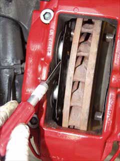 Note: Part numbers sometimes change without notice. Always double check with your supplier that you have the latest part numbers. Parts you will need: 1 set 996 352 949 03 Front Brake Pads - Porsche (Pagid "S" Pads - Dark Blue - T5104SRS14) 1 set 996 351 088 01 Front Vibration Dampers for Brake Pads (recommended) 2 ea 996 351 959 00 Front Pad Repair Kit (consisting of 2 bolts, springs and securing clips) 2 sets 996 612 365 00 Front and Rear Wear Sensors (if needed) 1 set 996 352 939 03 Rear Brake Pads - Porsche (Pagid "S" Pads - Dark Blue - T5105SRS14) 1 set 964 352 096 01 28 mm Rear Vibration Dampers for Brake Pads (recommended) 1 set 964 352 096 00 30 mm Rear Vibration Dampers for Brake Pads (recommended) 2 ea 996 352 959 00 Rear Pad Repair Kit (consisting of 2 bolts, springs and securing clips) Tools you will need: Jack 19 mm socket for wheel bolts Brake Parts Cleaner (do not use other cleaners) Needle Nose Pliers Punch (for driving the pins out) Hammer or soft mallet Caliper Spreader or large Water Pump Pliers Note: The brake pads must be replaced (both sets of pads per axle) if the brake pad warning indicator lights up, but no later than when there is a residual pad thickness of 2 mm. If brake pad wear is indicated by the warning light, the warning contact sensor (sender including wire and plug connection) must also be replaced. Replacing the warning contact sensor can be avoided by replacing the brake pads no later than when the pad thickness is 2.5 mm. Warning contact sensors with a worn wire core must be replaced. However, if only the plastic part of the warning contact is worn, replacement is not necessary. Also, do not disassemble the caliper when changing the vibration dampers (or painting the calipers) as Porsche does not sell inner seal kits. Jack up the vehicle at the lift points provided and remove the a wheel (you will need to do this for each wheel). Visually inspect the brake pads for wear. The wear limit is reached when the pad has a residual thickness of 2 mm (or less). Front Pad Replacement Remove the retainer (arrow) and extract the retainer pin inwards. Pull out the warning contact wire on the brake caliper and remove the warning contacts from the brake pad plates. Remove brake pads with a brake pad puller or use the water pump Pliers to spread the pads. (Photos are courtesy of Greg Heumann) Important Notes: Pull out brake pads together with the vibration dampers. If this is not possible (depending on wear of the brake pads), use a spatula to detach the vibration dampers from the brake pad plate before removing the pads. In both cases, first set back the brake pads as far as possible with the piston resetting fixture. If necessary, first remove some brake fluid by suction from the brake fluid reservoir. If necessary, carefully push back the piston to its original position. Fit new vibration dampers in the pistons. Do this by removing protective film from the vibration dampers before installation. Insert the brake pads. Caution: The pad backing plates (rear side of the brake pads) must not be greased. Note: If you are using Pagid (or some other 3rd party pads) you will likely have to drill the pad for the wear sensors. Just look at the old pads and drill the sensor holes in the same location. Fit new expanding spring, new retaining pin and new retainer (retaining bracket). These parts are available as a repair set and must be 'renewed' each time the pads are changed. Insert the warning contact wire and warning contacts. Firmly press the brake pedal several times with the vehicle stationary so that the brake pads assume their fit in accordance with the operating state. Next, check and, if necessary, correct the brake fluid level. Bedding in the brake pads New brake pads require a bedding-in period of approximately 125 miles. Not until then do they achieve their best friction and wear coefficient. During this period, the brakes should be subjected to full stress only in emergencies when traveling at high speed. ------------------------------------------------------------------------------------------------------------------------------ Rear Pad Replacement Remove the retainer (arrow) and extract the retainer pin inwards. Pull out the warning contact wire on the brake caliper and remove the warning contacts from the brake pad plates. Remove brake pads with a brake pad puller or use the Water pump Pliers to spread the pads. Important Notes: Pull out brake pads together with the vibration dampers. If this is not possible (depending on wear of the brake pads), use a spatula to detach the vibration dampers from the brake pad plate before removing the pads. In both cases, first set back the brake pads as far as possible with the piston resetting fixture. If necessary, first remove some brake fluid by suction from the brake fluid reservoir. If necessary, carefully push back the piston to its original position. Fit new vibration dampers in the pistons. There are 2 sizes of vibration dampers. The lower piston is 28 mm (smaller) and upper piston is 30 mm (larger). Be sure you get them in the right places. As you install them you will need to remove the protective film from the vibration dampers. Insert the brake pads. Note: The pad backing plates (rear side of the brake pads) must not be greased. Fit new expanding spring, new retaining pin and new retainer (retaining bracket). These parts are available as a repair set and must be 'renewed' each time the pads are changed. Insert the warning contact wire and warning contacts. Firmly press the brake pedal several times with the vehicle stationary so that the brake pads assume their fit in accordance with the operating state. Finally, check and, if necessary, correct the brake fluid level. Bedding in the brake pads New brake pads require a bedding-in period of approximately 125 miles. Not until then do they achieve their best friction and wear coefficient. During this period, the brakes should be subjected to full stress only in emergencies when traveling at high speed.12 points
 -
There have a been a few occurances of the cabrio top not fully completing the cycle, or simply refusing to open or close. If the hand brake light is on, very likely it is a low hydraulic fluid condition. The work below shows step by step how to add the fluid to the system. Tools needed: 5 mm allen wrench Flat screwdriver Children medicine syringe with small hose 1 Bottle of hydraulic fluid. Porsche is the recommended, I have used John Deere below with no problems after 4 weeks of filling: The steps for the process: 1. Open the top partially to the position shown 2. Pull the cables that the keep the rearmost part of the top secured to the car. One cable per side, the separate the cable from the connection in the car. 3. Let top move towards the close postion and move it out of the way. 4. Use a flat screw driver to remove the 4 plugs that keep the rear carpet in place. Remove the carpet, starting at the top as shown 5. Not a bad time to vacuum this piece while it is out. If you have kids, remove the lollipop sticks :P The work area will look like this: 6. This is the system pump you are looking for. Notice the screw where the Allen wrench will go to. Remove the screw, and keep a magnet pick up tool nearby if it fall down. 7. Use a flashlight on the oppsite side and shine direcly to the reservior. You will be able to clearly see the level and the gap to full. The fullmark is in the front below the screw removed. 8. To fill the top, use the syringe filled with fluid and insert the hose into the hole below. WARNING, the brass washer may fall off if you are not carefull, you can remove it or leave it and chance it. It probably won't move 9. Replace the screw, using fingers first to get it started. Take your time, will not be easy the first round. Finalize withe Allen wrench 10. Replace the carpet (did you clean it?) and the secure it with the plugs. Move the top back in place and secure the cables to the car. Open and close the top a few times. Enjoy the open air And remember, nothing races like a Porsche, but nothing runs like a deer12 points
-
This DIY tutorial covers how to remove the intake manifold on the 3.6L V6 Cayenne. Removing the intake manifold gives you access to several parts of the engine that you may need to service. Disclaimer: Perform at your own risk. This is for reference only, I am not responsible for any damage/injuries that may occur from this procedure. Please do not attempt if you are not comfortable with doing work on your car or working around the fuel system. Work in a well ventilated area as you will be releasing a small amount of gas and fumes. Difficulty: 5/10 Estimated Time: ~2 hours If you’re getting a Durametric error code P0674, you likely have a bad PCV valve that needs to be replaced. An easy way to test a bad PCV valve is to unscrew the oil fill cap on the engine while it is idling. If you feel suction on the cap and/or the idle fluctuates once the cap is removed then your PCV valve is bad. The PCV valve is built into the valve cover so your options are to buy a whole new valve cover assembly (95510513500- ~$347) or buy just the PCV membrane (aftermarket $20-25) and replace it in your existing valve cover. To get access to the valve cover, you will need to follow this DIY article to remove the intake manifold first. Other reasons to remove the intake manifold are to service your fuel injectors or to make it much easier to replace the thermostat. The thermostat can be changed without removing the intake manifold (I did it twice), however you basically need to be a contortionist to reach the bolts to remove housing and you will scrape some knuckles along the way. Tools Needed: -Flathead screwdriver -Assortment of torx bits (T20, T25, T30, 6” long T30) -Pliers -Torque Wrench -3/8” ratchet set with various extensions and a universal joint -1 1/16” Deep socket -10mm Triple Square Spline Bit -Crescent Wrench -9/16” Open End Wrench -Dental pick Parts Needed: -Brake Booster Vacuum Hose- 95535557941 (your existing hose is probably brittle and will likely crack from removing it, I recommend getting a new one) -Lower Fuel Injector Seal Kit (3X) - 95511091000 (existing seals may be brittle and once you have removed the intake manifold, they may not seal properly upon reinstallation, I recommend getting new ones, need 3 sets) Procedure: First start by removing the plastic covers surrounding the engine. Using a flathead screwdriver, remove the quarter turn plastic trim fasteners. Rotate them in either direction by 90 degrees and pop them out. Be ready to catch them as sometimes they like to jump out. Next you will need to remove the 2 torx screws on either side of the engine cover with a T25 bit and the screw under the windshield washer reservoir cap with a T20 bit. Remove the oil fill cap and front engine cover by pulling straight up. They are held on by friction rings around a stud so pulling straight up will release it. Now that you have the covers removed, it’s time to remove the intake filter box and intake piping. Using your T25 torx bit, rotate the 2 screws until the dot on the screwhead lines up with the lower indication on the filter cover. Now gently use your pliers to pull them straight out. With your flathead screwdriver, pop up the two clips to release the filter housing. Pivot the filter house towards the passenger side of the car and remove it. Remove the engine air filter as well. Next, remove the wiring harness from the MAF sensor located in the middle of the intake piping. Loosen the clamp around the intake piping on the throttle body and gently work the intake piping back and forth until it releases from the throttle body. Remove the top bolt on the engine lift bracket and loosen the lower bolt with your M10 triple square bit. Then pivot the bracket towards the front of the car. Remove the bolt next to the throttle body with your M10 triple square bit. Then unplug the wire harness from the throttle body. Remove the top bolt from the bracket on the passenger side of the engine with your M10 triple square bit. Remove the vacuum lines from the intake manifold on the passenger side of the engine. One hose requires pliers to open the hose clamp, the other can be removed by hand if you squeeze the lock ring around the hose to release it. Next, from the passenger side, reach your hand around to the back side of the engine. There is a vacuum line that goes from the bottom surface of the intake manifold to the brake booster. You will need to pull the vacuum line fitting straight down to pop it out of the intake manifold. I don't have a good picture of it so here is a diagram of it. Pull down on the elbow fitting, not the hose. Also on the back side of the engine just behind the vacuum line you removed there is a bolt that needs to be removed using your M10 triple square bit. You are working blindly so locate the bolt first by feel and guide your bit to the bolt. Remove the 3 screws holding the actuator with a T25 torx bit. Slowly pull it straight out towards the front of the car. There is an actuator arm that attaches to a shaft on the passenger side of the part. Once you have enough clearance to reach your finger in there, you need to slide the arm off the shaft as you pull the entire actuator off. Then disconnect the vacuum hose from the actuator. Now pull the coolant hoses out of their holder in the intake manifold and push it towards the driver side of the car. There is a T25 torx screw that attaches this water hose bracket near the back of the intake manifold. The screw is facing up, so you need to use your T25 torx bit and get creative with removing that screw. I used a crescent wrench to turn the torx bit while holding the torx bit in place with my other hand. With the water hose bracket free, slide the water hose bracket towards the front of the car to release it from the intake manifold. This bracket has a keyhole slot that will release once it's slid forward. Remove the oil dipstick tube bracket with a T25 torx bit. Just push it out of the way once you remove the screw. With your long T30 torx bit, remove the bolt on the intake manifold that was under the actuator. Next, there are 3 blind holes on the driver side of the intake manifold. You need to use your long T30 torx bit to loosen the screws inside those holes. Those 3 screws are captive screws so they will not come out. There are 3 bolts below the intake runners. They need to be removed with your M10 triple square bit. This is where your universal joint will come in handy. The bolt near the rear of the engine required me to use my u-joint with various entensions to acess. At this point, you will hear gas leaking out. Since you have released the pressure from the lower fuel rail to the lower fuel injectors, the pressurized gas in the rail will leak out. Make sure you are working in a well ventilated area. From the driver side of the car, reach behind the engine to remove the wire harness from the fuel pressure sensor. Using your 1 1/16” deep socket, unscrew and remove the fuel pressure sensor. Using your 9/16” open wrench, unscrew the nut that connects the metal fuel line running from the lower fuel rail. The slimmer your wrench the better. My crescent wrench did not fit here. Now that the intake manifold is completely unbolted, you can start to wiggle it free. You will need to lift the manifold up from the passenger side and pivot it up towards the driver side. You will need to wiggle the lower fuel rail loose to release the metal fuel line you just unscrewed the nut from. It is a flare fitting that pushes into the upper fuel rail assembly. Be gentle here as you don’t want to bend the fuel rail. Once the metal fuel line is free from the upper assembly, you can remove the intake manifold as described above by lifting up from the passenger side first to pivot it off. At this point, you have access to the fuel injectors if you need to service them, the thermostat housing and the valve cover. Unbolting the valve cover is straight forward from here if you need to replace the PCV valve, etc. The fuel injector seal kit comes with a rubber o-ring, Teflon o-ring, Teflon sleeve and metal clip. At the bare minimum you should replace the rubber o-ring and Teflon o-ring. Use a dental pick to remove the old o-rings. These 2 parts are the wear surface when you remove/reinstall the intake manifold and are prone to fail if you re-use them. Trust me, I learned the hard way. To install the intake manifold, reverse the steps above. Take care in sliding the lower fuel rail back onto the lower fuel injectors and lining up the metal fuel line back into the flare fitting. I found it was easier to pull the lower fuel line out of the manifold to line the flare fitting up first, then pushing it into place in the intake manifold. You want to apply even pressure on the surface as you tighten all 7 of the bolts down on the driver side. Torque the 3 triple square bolts evenly to 6 ft lbs, torque angle 90 degrees, then a final torque of 22 ft lbs. The bolts holding the engine lift bracket are 17 ft lbs, the other triple square bolts holding the manifold on the head are 15 ft lbs. Once you get it all back together, turn the key to the ON then START position without your foot on the brake. This will run the fuel pumps to build pressure back up in the fuel rail. I removed the key and repeated 2-3 times to get the fuel pressure up. The first time you restart, it may take a couple seconds to fire up due to the fuel pressure needing to build back up. If you replaced your PCV valve, it may idle rough as the ECU needs to remap since it adapted to a leaking PCV valve over time. If you did not replace the fuel injector seals and smell gas/hear it leaking after shutting off the engine, then your seals failed and you need to repeat the procedure and replace those seals.11 points
-
EDIT: Fixed text boxes to see text better. This is an AOS DIY that walks you through the process of replacing the AOS. This is for a 2000 996 C2 Cab, six speed. I tried to be as thorough as I could in writing the DIY. If there is something left out or lesson learned from your personal experience with the AOS and or this DIY, please let me know so I can incorporate it into the document. Regards, Ken How do you eat an elephant? -- One bite at a time! Air Oil Separator Replacement.pdf11 points
-
The credit for this goes to Kendo on 986forum, but I thought it might be worth posting in the DIY section here. I tried it and it worked for me. Kendo: For those that have just had the tactile switch fail and want to replace it it can be found at Mouser Electronics for $0.60 each. Tactile switch The item you want is figure "C" 101-TF25R-EV (at least this is true for the three button key FOB head on my 2004 key). I used the 400 gf switch for my failed unlock button, but comparing the operating force to the stock switches I think 300 gf would be closer to correct. BTW the description says it is a thru-hole part. This is incorrect it is surface mount as shown in the picture. De-Soldering and soldering this piece is easy. Just use a soldering pencil (get one at radio shack cheap) rather than a soldering gun.11 points
-
I have modified the rear storage compartment to handle two (2) 5" subs and two (2) 4" speakers. I will be using Focal speakers, the 5" 13KS subs and a pair or 4" 100CA. The Focal 5" subs are the best sounding subs that I've ever heard. I have spent weeks cutting and shaping this compartment and its finally ready to make the master mold. I will be selling these Rear Speaker/Sub Boxes in the very near future if anyone is interested. They will have a gelcoat finish and I'll make a few colors. I have attached a couple of photo's of the prototype so you can see what it looks like.11 points
-
Instructions below:11 points
-
Which radios fitted to Porsche can have their unlock code recovered through serial number? - CR-220/CDR-220 - Becker - CR-210/CDR-210 - Becker - Traffic Pro NAV/CD - Becker Which radios can not have their unlock code recovered through serial number? - CR1 - Alpine - CDR-23/24 (or later) - Becker - PCM (Porsche Communication Management) – Siemens & Becker How to get your radio serial number? CR-220/CDR-220: Hold down the TP button for at least 10 seconds after you turn the radio on. "Becker 1" will be displayed. Rotate the right knob (slowly) and it will display the Becker model number. Then rotate it again and the serial number should be displayed on the radio. Or, if the radio is out of the car the then the serial number is on the label. CR-210/CDR-210: Press tone, then 8 and 0 simultaneously. "Becker" appears. Press station up arrow on right. "PR-VERS" appears. Press one of the numbered buttons below the display, directly below the LCD arrowheads (try a few). The model number will appear. Press station up arrow on right. "SERIAL N" will appear. Press the numbered button again. The serial number will appear. Or, if the radio is out of the car the then the serial number is on the label. CDR-23 (or later): These radios do not have a security code - that is, not that the user enters. These radios are security tested on the MOST (fiber optic bus) system to see if they are the "programmed" radio. The radios are programmed and recognized by the car’s DME and can only be replaced by a shop with a PST2 or PIWIS. These radios will not request a code when battery power is disconnected. Traffic Pro: Select the Service Menu, press NAV and multifunction key 10 simultaneously in radio mode. Use multifunction keys Nxt and Prv or turn the right control knob to select the individual items. You can move through the following items: - Model-No. - Serial-No. <-- this is what we need - Changer Reset - GAL - Radio Software - Radio Bolo - Navi Rom - Navi Flash - RTC Value To quit the service menu, press END. I get a WAIT on the display - what do I do? You have to wait at least 30 minutes before trying again. The suggested number did not work - what do I do now? Most often when the code we give you does not work it is because the serial number came from an old card in the car rather than from the procedure stated above - or a typo in the serial number submitted. Double check the serial number you submitted using the procedure above again. If that does not work then you will need to contact a dealer or Becker. Becker charges to look up your code and some dealers also charge. Our program works maybe 99.9% of the time but we have no explanation why it doesn't always work. Can you give me a code for my PCM? These units are manufactured jointly by Siemens and Becker, and the only place where you can get the codes required is from the dealer/OPC. The PCM’s require two codes, the ICS/Siemens code, and a Becker code. The ICS is the first code requested. Sorry, the only place you can get a PCM code is from a dealer/OPC. Can I post my VIN to get a code? We do NOT need your VIN - only your radio serial number. Where can I post my lost code request? Please post your request here: Lost Radio Code - post your request here Please DO NOT PM me or email me (or anyone else helping with the codes) your radio code request - we will only answer requests in that one thread.11 points
-
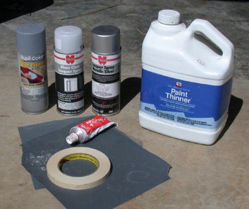 Courtesy of Nasa Racer Pete (used with his permission) - posted by Loren Well, there I was...backing into a parking space against a curb and I was in a hurry and I heard it...SCRAPE! One fraction of a second...barely moving. Got out and looked at the rim...OOOOOOWWWWW! Well, no need to fear...I've done this enough times to have a easy way to do home repairs with a few simple items. Note that this ONLY covers light scuffs, this isn't meant to be used to repair a DAMAGED wheel or one where the scuffs cause significant damage to the rim. This is only for those annoying superficial scuffs like happened to me more times than I care to admit. Now there are PLENTY of GOOD services which can do this for VERY reasonable money...most folks will happily do this but I'm inpatient and have the free time (generally) to spend a couple of hours doing this and it REALLY takes the edge off donking my wheels when I know I can simply fix it myself. So if you are interested...here's what you need: I have a can of scratch-filler primer, the WURTH wheel paint and clear (got mine at Performance Products), some paint thinner, Bondo spot putty (or equivalent), sand paper and some 240 and 400 grit sandpaper (if you are REALLY anal...get some 600 grit). Step 1. Clean...clean...clean...and did I mention CLEAN! This is one of the most important steps. Use paint thinner to THOROUGHLY clean the ENTIRE area around the damage...you need to get ANY wax or polish or anything off the wheel...I'm going to remind you EVERY step...I probably end up wiping down these surfaces 10 or more times before painting...if you don’t do this, the rest is pointless. Also, we want to work ONLY on the area that's damaged...don't go nuts and try to paint half your wheel on the car...for this technique to succeed we want to sand and paint the area only IMMEDIATELY around the damage. 2. Sand and Putty I like to START by masking the tire from the wheel...get the masking tape WELL behind the rim. Next, sand the area to a nice "feather" with 240 grit sandpaper and wipe some spot putty on. IMPORTANT...this ENTIRE project will work best if the wheel is in the sun and its a nice warm day...the drying time of spot putty is minutes but if it's cold or damp, this project is likely to not work out too well. Remember...keep your sanding to the IMMEDIATE area around the damage. Trust me on this. So once you've done the first round of putty, switch to the finer of your sandpaper (400 grit in my case) and sand and putty until it FEELS and LOOKS flush. Note that I use the paper wrapped around a piece of wood to make a flat sanding block. It's best to sand with a flat block to get the smoothest finish: Note that up to this point...including waiting 5 to 10 minutes between coats of putty that the whole project has taken about 40 minutes. 4. Masking and primering: Okay, here's where a bit of laziness is going to create an entire new clay-bar project. This metallic paint will GET EVERYWHERE. I'm talking permanently attached to the fender on the opposite corner of the car...mask CAREFULLY and COVER THE WHOLE CAR with a sheet or equivalent. I've used the thick scratch-filler primer and sanded it and put a bit more putty on. Note that this is the first place where I use the NASA technique. Immediately after I spray the primer (or paint) I clean ALL the overspray off the spokes of the wheel (clean rag and paint thinner) and the area around the inside of the rim...I do NOT want to try to get paint to smoothly adhere to the entire wheel! We just want to paint the REPAIR. Only the clear coat will be sprayed without wiping off the overspray. Wait for the primer to fully dry and lightly sand it with 400 or 600 grit sandpaper. 5. Painting VITAL: READ THE CAN...if you try to use this paint in cold temperatures (or in damp conditions) it’s going to be a mess...shake the can for a minute at LEAST and push the spray nozzle as you sweep across and release at the end. This is roughly the distance I used the can from the wheel...I HIGHLY recommend painting some scrap something to get used to the distances and thickness this paint sprays. Now we SHOULD be nearly done BUT (as always) Pete got inpatient and sprayed the clear WAY too soon and lifted the paint and messed it all up. This is NO BIGGIE...take a deep breath, get out your rag and the paint thinner and take it all off. The thinner I used did not eat into the primer so I simply cleaned the wheel (again) and got to respray the silver. Here’s the paint lifting because of the clear being sprayed too soon. okay, fast forward a few minutes...I had to roll the car forward a bit to keep it in the sun and I had cleaned (and let fully dry) the wheel and RE-sprayed the silver. Now I’m using the NASA technique on the silver paint and CAREFULLY removing the overspray: AND here’s the nicely painted wheel. I’m going to not be an idiot and let the paint dry OVERNIGHT (like I knew i should) and do the clear coat tomorrow. (edit June 14, 2004 added local hosting of images as Nasa Racers hosting was down - Loren)10 points
 -
I had heard this urban legend that you can repair door dings and dents by rubbing dry ice over the dent and then heating it with a hair dryer or heat gun. It seemed simple enough, so I decided to try it on the wife's urban assault vehicle which has its fair share of door dings. I went over to our neighborhood grocery store and got 2 pounds of dry ice for $3. Here is the what the test door looked like before the test. Essentially the process is to take some dry ice (while wearing gloves, as it is very, very cold), and simply run the dry ice back and forth over the dent until the metal has cooled to the temperature of dry ice. This shrinks the sheet metal, and pulls in the dent. Next blow hot air onto the dented area using a hair drier or a heat gun making sure that you don't heat the sheet metal to over 195 ~ 200 degrees as you can damage the paint by heating any more than that. This will expand the metal and further smooth the dent. After you have the sheet metal hot, then run the dry ice over the dent again until the metal is cooled to the temperature of the dry ice again. It takes about 3-6 times of this hot-cold-hot-cold routine to get complete results, but you will start to see the dent go away after the 1st cycle. Repeat this process until the dent is gone to your satisfaction. Your end result should look like this: This trick works even better with aluminum panels, does not scratch, discolor or harm the paint because the face of the dry ice on the sheet metal has a thin layer of Carbon Dioxide gas that is boiling off from the frozen dry ice. I next tried this technique on the 996 with a small ding on the left rear quarter panel, and it worked perfectly. So $3 worth of dry ice and about 30 minutes saved me several hundred dollars for a paintless dent repair guy to do essentially the same job.10 points
-
The symptoms for this include CEL and Long Cranking times when starting after filling up. Part Required 948 110 202 01 (75 from dealer, 45 from Sunset) Some new Twist locks for the trim panels, since they have a mind of their own. You will need to remove the throttle design cover pull up it comes right off. then you will need to remove the 4 t 30 torx screws on the drivers side coil cover. then that cover will pull up although it is a pain, you can wiggle it out. Use a large flat blade screw driver or a penny to remove the 1/4 twist locks that hold down the drivers side engine compartment cover (the big black one) there should be 4 1/4 ttwists Then remove the rearblack panel, 1 1/4 twist in the center and 2 on the pass side of it. Remove the panel the purge valve is in the front of the engine between the head and the intake on the drivers side. It looks like a black cylinder little bit bigger then a film canister with a hose on one end to the front and the back is a hard black plastic line that runs along the intake and comes up in the back and goes to a rubber hose on the fire wall. Un plug the valve and push it off its bracket, undo the clamp with a pair of plairs and pull the hose off (sometimes you need gently grab the hose with the pliars and twist to loosen it up from the valve, you can damage the valve just not the hose). In the rear you will need to do the same, the rear hose never comes off easy I think they glue it on, use you pliers to crush the plastic line where the hose is over it. once it is crushed enough it will come off with needle nose pliers. Undo the injector electrical connections (wire clip on each) and pull them off, also free the ratcheting clip on the 1 inch flexy pipe crossing over the top. These 2 steps make removing the pipe a lot less violent. I did not and I would do the next time (hope not) I would cut the pipe after you have sprung it out of the gold clips along the intake, it make it easier to remove The pipe has some sleeving which is re-used, see when they are before you remove and put them back the same The hard part is the removal, putting it back is a piece of cake., Dont forget to hook a durametric to clear the code. I filled up for the first time this morning, perfect start afterwards. I need to give credit for this to a certain dealer tech from Miami (Firehawk) without whose help I would not have been brave enough to do this myself.10 points
-
I am posting some notes as to my process in removing the rear half axles from my 2000 Boxster S, and replacing the CV Joint “Boots”, both inner and outer. I hope this will be of use to folks, and I want to acknowledge the good assistance from those on this Board who helped along the way: Note: For tools, you will need a large torque wrench. I bought mine from Harbor Freight for $79.00. I’d highly recommend not only that wrench, but a good set of metric wrenches and sockets, a NAPA CV Boot clamp tool, and a good set of snap ring or “circlip” pliers. I'd also suggest a ball joint separator tool. I’ll leave it to you, but when you order your new boots and clamps, you might want to order new CV Joint end caps, new snap rings/circlips, new hex head bolts for the CV Joints, and definitely new axle nuts, and perhaps a few extra nyloc nuts for the ball joints discussed below. Here is the process I followed: 1. Remove Porsche emblem hub center pieces using a 90 degree bent awl, or similar tool, and loosen, but don’t remove, the 32mm axle nut on each rear wheel axle. 2. Block the front wheels and raise the rear of the car from the middle rear jacking point approved by PCA and Bentleys, just rear of the engine oil sump, where the two bolt heads fastening the under-pan to the frame support appear. 3. Place a sturdy jack stand under each rear jacking point, using a rubber pad or jack stand pad (from Harbor Freight or elsewhere) to protect the car, leaving room to access the forward bolt from the diagonal cross arms on the underside, and gently lower the car onto the stands. 4. Remove each rear wheel and remove each 32mm axle nut, and slide wheels under each side of car as an added “catastrophic” precaution in case the car should somehow fall from the jack stands or should a jack stand collapse. 5. Remove diagonal underside cross arms and under-pan. 6. Remove bolts from each side of sway bar and swing out of way. 7. Remove six hex-head bolts from each inner CV Joint half-axle, and let each axle rest down on the exhaust pipes. Note: Use a nine inch ratchet extension and a good 8mm hex head socket fitting, loosening one bolt at a time, and using the parking brake for each bolt to keep the wheel hub from rotating. The 9 inch extension will help to achieve access to each bolt with the CV Joint Boot kept out of the way. Release the brake to rotate to the next bolt, then reset the brake. 8. Remove each nut from toe-in/track arm at the side of each wheel carrier, then separate ball joint with a ball joint separator tool (Harbor Freight) and, using hand pressure only on the track arm, push the ball joint pin out of the wheel carrier. 9. Remove nut and bolt from the trailing arm to the middle of the control arm, and slide the forked end up the control arm to allow movement 10. Remove nut from control arm ball joint and separate ball joint from control arm. You may have to hold the ball joint pin firmly in place with a torx/star or similar fitting into the top of the pin. 11. Mark the position of the control arm eccentric bolt on the inner mounting point on suspension frame, then loosen, but do not remove the eccentric bolt or the nut on the opposite side. 12. The control arm should now fall freely out of the wheel carrier 13. Pull each wheel carrier out a few inches and place a brace of wood (I used a 1.5 inch square piece, about 13 to 16 inches long) behind the heavy structure of the wheel carrier, squeezed between that carrier and the frame bracket of the control arm. Do this one wheel at a time, not together. The purpose is to hold the wheel carrier outward and firmly in place while you remove the axle from the wheel carrier hub as explained below. 14. Now that you have enough clearance with the wood braces, pound the axle out of the wheel carrier by using a good heavy hammer, perhaps 5 pound one, and buffering the blow to the axle with a small block of wood, perhaps 1.5 inches square and a few inches long. The axle will pop right out. 15. Now remove the wood brace spacer (the 13 to 16 inch one), but realize you must now grab each wheel carrier, pull the carrier out, even farther than the wood spacer accomplished, and remove the axle from the car. A good firm pull is required, and remain confident that neither the brake lines nor the strut will be harmed by the process. 16. Place each axle being worked on in a good vice or on a bench where it can be confined. Tap off the inner end cap, remove the steel snap ring (actually called a “circlip”) with special needle pliers, tap off the CV Joint, in all cases using a piece of wood as a buffer, and then remove the boot clamps and both the inner and outer boots, and clean out all old grease and ascertain that no contamination exists. Then in proper sequence slide the boot clamps and new boots back onto the axle, and repack with CV Boot grease. Be careful not to force grease into the bolt holes of the six hex-head bolts; otherwise, the grease may contaminate any loctite or similar product used when you “re-torque” the bolts at the transmission flange. Also, if you disassemble the inner CV Joint, remember that the ball hub has a camfered inner end that must face toward the axle after you re-grease it and install it into the ball cage, then into the CV Joint. 17. Reassemble in reverse. Torque all fittings. Use loctite where appropriate. You may need to use a jack under the control arm when re-fastening the control arm ball joint nut. When re-tightening the eccentric bolts at the control arm, be sure the markings remain lined up. 18. Only torque the axle nut to 100 foot pounds while on the jack, and even then only carefully. After replacing the wheels and lowering the car, bring the torque to 340 foot pounds, drive the car a few miles and recheck the torque again. Then replace the emblem caps. I hope this helps someone. I’m posting it only because I had some difficulty in my own process, and felt some of the detail here, though perhaps different than offered in other posts, might be useful. The attached drawing will be of assistance in identifying parts involved. Follow all factory torque specs and other mandatory procedures. You may want to check rear wheel alignment when done as well. Good luck all. And use care to be safe. Marking eccentric bolt before loosening: Drawing of axle and control arm/ball joint components: Wheel carrier with axle pushed out: Greasing the CV Joints--the outer joint does not come apart, only the inner: Transmission flange for six hex-head bolts: Working on the removed axle: Removing circlip: Showing CV Joint End Cap to be removed for grease packing:10 points
-
 Note: Part numbers sometimes change without notice. Always double check with your supplier that you have the latest part numbers. (Edit - July 25, 2006 - Updated the clutch bleeding procedure to the latest procedure as outlined in supplement 98 of the Carrera Service Manual - Loren) Parts you will need: 1 liter (minimum) 000 043 203 66 Porsche DOT 4 Brake Fluid or equal (ATE Gold or ATE Super Blue) Tools you will need: Jack 19 mm socket for wheel bolts Motive Power Bleeder (or equal) image Needle Nose Pliers 11 mm wrench for brakes; 9 mm for clutch slave (sizes vary from car to car but they are usually 9 mm or 11 mm) Plastic tubing and waste container (at least 1 liter) Jack up the vehicle at the lift points provided and remove the rear wheel (you will need to do this for each wheel). Remove the cap on the master cylinder reservoir. Remove the plastic screen using a pair of needle nose pliers. This can be a little bit challenging but it will pop off (be careful with the brake fluid.. it eats paint!) Use a syringe (or turkey baster... just don't reuse it) and suck out as much of the old fluid as possible. Fill the master cylinder reservoir with new fluid. Put the rest in the power bleeder. Screw the cap that came with the power bleeder onto the master cylinder reservoir. Put the pressure cap with the pump handle on the power bleeder and pump it up to just under 20 psi - do not go over 20 psi! Bleed order - Right rear, Left rear, Right front, Left front. Place your drain tube over the outside bleed nipple and in the bottle (remember it will need to hold a liter when you are done). Bleed the outer bleeder valve first. Open each bleeder valve until clear, bubble free brake fluid emerges. Take care to bleed at each brake caliper and at both bleeder valves. Carefully tighten the bleed screw. Wipe off the area and replace the rubber protective cap over the bleed screw. Repeat steps 8-10 for the interior bleed screw. Then reinstall the wheel and move on to the next wheel. Note: It makes sense to check the pressure and amount of fluid in the tank between wheels. Running out of fluid means starting over and getting air out. Optional Clutch Bleeding This is best done when you are bleeding the left (driver's side) rear wheel as the clutch bleed valve is mounted high above the axle on the transmission. Push the clutch pedal in by hand (very slowly) and use a long piece of wood to hold the pedal down. I wedged the other end (of the wood) between the seat and door frame -- with plenty of soft padding to avoid scratches. A second option is to have a 2nd person sit in the car and keep the clutch pedal FULLY depressed. Open the clutch bleeder valve until clear, bubble free brake fluid emerges (at least 30 seconds according to Porsche). Remove the wood. Then, pump the pedal again very slowly by hand for a further 60 seconds. After pressing the pedal down fully about 10 to 15 times, leave the pedal in its normal position. After allowing a fill time of 90 seconds, check that no more air bubbles appear at the bleeder valve (use a collecting bottle with a transparent hose). Then close the bleeder valve. Wipe off the area and replace the rubber protective cap over the bleed screw. You may notice that the clutch pedal does not return... so carefully pull it up (slowly) to it's normal position. Then depress it (slowly) a few (at least 5) times. In a few cycles the feel should return. [*]Torque the wheels bolts to 96 ftlb. (130 Nm). [*]Do a final check on the brake fluid level and top up if needed.10 points
 -
Eureka! I suppose during the time you guys were typing, I was arriving at the same conclusion. I pulled the latch mechanism out and examined it up-close. The tension spring was out of a pocket on the latch and not providing any push when the latch was released. Hence, the hood could be pulled up out of 'battery' but would not pop up on its own. I disassembled the mechanism, lubed it, and re-inserted the spring into the latch. Put it back together and now all is well. Very simple to do. This is how I did it and you may find it useful. Do so at your own risk, yada yada yada. 1st, open the hood and peel back the carpet cover just inside of the latch. Next, using a flat-head screwdriver, remove the four plastic 'screws' holding the trim plate between the bumper and the hood flange. They merely turn 90 degrees (so that they are perpendicular to the car's direction of travel) and pop out. Then remove the trim piece and place to the side. Next, using a ten millimeter socket, remove the two bolts securing the latch to the car. They are located just inside the trunk under the carpet you just peeled back. Once they are removed, the latch is now only held in place by two metal cables and the alarm pin switch wires. Carefully unplug the alarm wires. Push in on a small 'latch' on the lower half of the plug and pull out the lower half. Then carefully rotate the upper half about 45 degrees (it should be fairly easy to move, don't force it) and the plug will pop out of the metal holder. Then use a small screwdriver to gently push a release clip on the plastic mounting point. This will allow the small plastic mount to separate from the wiring plug. Now you need to gently remove the cables from their sockets. Take the tension off of the upper cable and gently pull the cable up out of its socket. Then remove the lower cable in the same way. The only thing holding the latch in the car now is the alarm wiring harness. Push the rubber grommet through the body toward the bumper. You can then pull the wiring through and the entire latch will come out of the car. Be sure to set the stainless steel shroud to the side. It was not attached on my car but may be on yours. Now that you have the latch out of the car, you can see the large diameter steel spring that is wound around the large post to the passenger side of the latch. That is the culprit. The small plastic shroud over it pulled straight out and off of my latch. This is the microswitch that tells the alarm that the trunk is open or closed. Set it to the side. You should now see the latch mechanism and the hole that the spring needs to be in to function properly. I used two screwdrivers to push the other end of the spring (the end on the release / catch mechanism ) over the catch. This allowed me to push the end into the latch more easily. I then popped the spring back over the catch. Now there should be tension on both the latch and the catch. Lubricate with white lithium grease, or some other semi-solid lubricant and work the mechanism to ensure that it is functioning properly. Once you have confirmed proper function, reassemble in reverse order (i.e. put the alarm switch back on - it should snap right back in place ), pop the cable back on, thread the wiring through and secure the grommet in place, place the stainless shroud on, insert the bolts and loosely tighten things. Once the bolts are in, line up the hood and the latch mechanism and tighten down the latch. Replace the plastic bumper/body trim piece but don't insert the 'screws' until you've tested the hood a couple times. Once it is clear that the hood is functioning properly, secure the trim, replace the carpet and smile at a job well done, for free. If I can figure out how to transfer my pictures out of my camera phone I'll add some illustration to this. Hope this helps. I was frustrated as *)*^*( until y'all help me realize what the problem was. Pictures ...9 points
-
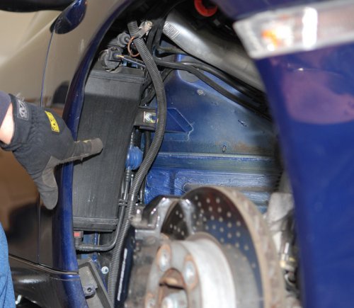 Note: Part numbers sometimes change without notice. Always double check with your supplier that you have the latest part numbers. (Special thanks to Chuck Jones for being the guinea pig and for taking the photos.) Parts you will need: 997.624.113.00 Actuator Tools you will need: Very short Torx T20 driver and right angle ratchet or tool to use the short T20 in a very confined space Regular screwdriver, phillips screw driver, and 10 mm wrench to remove th wheel well liner 1. Jack the car so that right front wheel is off the ground and secure it with a jack stand. Remove the right front wheel. 2. Remove the wheel well liner by removing the the plastics rivets (pry them out with a regular screwdriver). As well remove the 10 mm nuts on each side of the axle. Now remove the phillips screws that fasten the wheel well liner under the front bumper and remove the wheel well liner (and set aside). 3. Locate the EVAP canister and remove the electrical connection at the top of the canister. Now remove the 10 mm nut that holds the canister in place. Remove gas the vapor lines - one at the top and one at the bottom (again by squeezing the connectors). Remove the EVAP canister by pulling gently back and forth until it releases from the rubber gromments 4. Look back up under the fender (now that the canister is out of the way) and locate the broken actuator. Now using the stubby Torx T-20 loose (but do not remove) the two T-20 screws. The actuator itself is a bit tough to get to and you will need a really short T-20 Torx head to loosen the two screws. I say loosen because that is all you need to do to remove the part - it sits in two "U" shaped slots. Remove the electrical connector (by squeezing the tab). Here is a pic of the new part - as you see the Torx screws are already in place so that is all you have to do to replace it. 5. Put the new part in place making sure you feed the emergency pull line through the fender to its location in the door jam. There is room to slide it through the side so you don't need to try and thread it through the hole. Fasten the two Torx screws and reconnect the electrical connector. Chuck's car had the guide rose guide piece missing (so he needed to order one) Here is a pic of his car (without guide rose) and my car (with guide rose). Ref. P/N 997.624.505.00 We also noticed that on his car the plastic catch for the lock was missing (so he needed to order that too). Here is a pic of his car (without cap) and my car (with cap). Ref. P/N 996.201.243.00 6. Reinstall the EVAP canister by pushing it into place on the rubber gromments. Then reattach the vapor lines (they should snap back into place) and the electrical connection. Finally put the 10 mm nut back in place and tighten down. 7. Reinstall the wheel well liner (reverse of removal). 8. Mount the tire, lower the car and re-torque the wheel bolts. Done.9 points
 -
 Covers all Carrera, and GT3 cars Removal -- 1. You will need to lift the car high enough that you can safely get underneath (you do not need to remove the rear wheels on most cars but most folks find it easier with the rear wheels off). 2. Loosen the 2 bolts (each side) on the sleeve that connects to the cats and then slide it towards the cat. (You might want to spray these nuts with WD40 first so they will loosen easier -- just don't spray the O2 sensors). 3. Crawl under the car and remove the 3 bolts that hold the muffler mounting bracket and the muffler in place. These can be a bit of a reach and not much swing room for the wrench. 4. Rotate the muffler down and out from under the car. 5. Remove the tailpipe by loosening the clamp as you will need to use them on the new mufflers. Install -- 1. Attach the tailpipe(s) to the new muffler but do not tighten them yet. You will need to adjust everything later before you tighten them down. 2. Rotate the muffler up and on to the 3 bolts and lightly tighten the nuts. 3. Slide the sleeve off the cat and realign it on the muffler and cat. Again, don't tighten the nuts too tight yet. 4. Align the tailpipe so that there is about 20 mm distance from the top of bumper cover and equal distance and length all the way around. Then tighten down all of the nuts. The tailpipe 22 ftlb. (30 Nm ), cat sleeve 34 ftlb. (46 Nm), and the muffler bracket 17 ftlb. (23 Nm). 5. Repeat on the other side and you are done! (updated with torque values and images 26 Jan 2004)9 points
 -
I read other threads regarding removal of the Cup Holders. Haven't seen one with pics, so I took a few shots and hope can help a bit... I hate these Cup Holders... They feel sticky most of the time, but it's part of their construction... This is part of what I did recently (15 Sep 2010). Hope it helps and it's just a guide and 1st post. I'm no expert, so work safe and with patience... So Pics are: 1, 2 3, 4 and so on... Pic #1 - Front Console [a.k.a. Horse Shoe]. Pic #2 - Insert something plastic at the bottom and pull . Pic #3 - Pull and twist to the left [You'll do the same with right side, but will twist right] Pic #4 - Insert again your plastic tool in the Cup Holder's bezel and pull. Pic #5 - #7 - Work in progress... Pic #8 - Remove those 4 screws as shown.... Pic #9 - Pull out Cup Holders Pic #10 - Coca-Cola all over the radio!!!! Clean it.... Pic #11 - Oil or grease points shown. Yellow gears are the ones that slow down the Cup Holder when it goes out. The other [the second from left to right] it's the locking mechanism. I used the dielectric clear grease for spark plugs.... Very nice results.... Pic #12 - That's the Part Number printed on the Cup Holders, so if you decede to bought them brand new there's a reference for you... REMEMBER: My Boxster is Boxster S 2001....9 points
-
by drpaulmarsh, Ryan Hanson & Hans Wiederrich Note: Part numbers sometimes change without notice. Always double check with your supplier that you have the latest part numbers. Front Strut Removal and Installation: 1. Loosen lug nuts slightly and block rear wheels. 2. Remove the shroud on the trunk with a torx screwdriver. 3. Mark the location of the three (3) 13 mm bolts on the top of the trunk that holds the strut to the body with a ink pen. 4. Jack up the car and remove the wheels. 5. Loosen the 18 mm sway bar bolt that is on the bottom of the strut (counter with open-end wrench). 6. Take off the caliper from the hub. Don’t let it fall as it may stretch and break the brake line. (*Porsche recommends replacing the two caliper bolts and not re-using them) 7. Remove the nut on the strut spindle assembly, the abs wires and brake lines. 8. Remove the three (3) 13 mm bolts from the top of the trunk that holds the strut to the body. Peek down in and note the installed position of the spring strut mount. The arrow markings must point to the outer side of the vehicle (A). The shock absorber piston rod is thereby shifted outwards. 9. Now with a friend, push down the arm and gently pull towards you. The strut will be in the wheel well now. 10. This is the tricky part; my friend and I covered the strut top w/ a shop towel and carefully pushed down the strut and pulled it towards me to pull it out of the wheel well. Be careful not to hit/scratch the lip of your fender. (If it doesn’t go easily, you may want to try using a spring compressor to shorten it a ½ and inch or so.) 11. Once cleared you can wiggle or slide out the strut from the spindle assembly. Front strut disassembly and assembly: 1. Apply spring compressors to both sides and compress the spring a ½ inch or so. This may be difficult to do as the front springs are conical shaped, but will ensure that the nut on top is easily removed. 2. Remove the 21 mm nut on top of the strut. (item 1 in picture below) Counter the piston rod when loosening the nut. 3. Pay attention to how it comes apart. 4. Put all the necessary parts on the new strut (You will be re-using the old rubber bump stop so don’t throw them out) and assemble back wards. 5. The new springs are shorter so the assembly will not have as much tension. 6. Tighten the fastening nut to 59 ftlb. 7. Install the new strut in the reverse as described above and use the sheet below for torque values: Cross member/side member (one component) Location Thread Tightening torque [Nm] (ftlb.) Cross member/side member to body M14 x 1.5 160 (118) (Front and rear) Corner plate to side member M10 x 1.5 65 (48) Corner plate to body M12 x 1.5 100 (74) Corner plate to body M14 x 1.5 160 (118) (With diagonal arm and side member) Diagonal brace Location Thread Tightening torque [Nm] (ftlb.) Cross member/side member to body M14 x 1.5 160 (118) Diagonal brace to body and side member M12 x 1.5 100 (74) Axle strut (control arm) Location Thread Tightening torque [Nm] (ftlb.) Axle strut to side member M12 x 1.5 120 (89) Axle strut to diagonal arm M14 x 1.5 160 (118) Axle strut (ball joint) to wheel carrier M12x1.5 75 (56) (also applies to GT3 RS) Camber basic setting to two-part axle strut M8 27 (20) - 911 GT3 /911 GT3 RS Spring strut/wheel carrier Location Thread Tightening torque [Nm] (ftlb.) Spring strut to wheel carrier (stabiliser mount) - 911 Carrera 2 M12 x 1.5 85 (63) (shock-absorber tube clamp) - 911 Carrera 4/ M12 x 1.5 85 (63) 911 GT3 / 911 GT3 RS Spring seat clamp - 911 Carrera 4 M6 10 (7.5) Spring strut mount to body M8 33 (24) - 911 GT3 / 911 GT3 RS M8 35 (26) Spring strut mount to piston rod M14 x 1.5 80 (59) - 911 GT3 / 911 GT3 RS M14 x 1.5 80 (59) Stabiliser mating bearing to spring strut (lock nut) - 911 GT3M52 x 1.5 50 (37) Height adjustment to spring strut (lock nut) - 911 GT3/911 GT3 RS M52 x 1.5 50 (37) Brake cover plate to wheel carrier M6 10 (7.5) Brake disc to wheel hub M6 10 (7.5) Brake caliper to wheel carrier M12 x 1.5 85 (63)* Speed sensor to wheel carrier M6 10 (7.5) Combination coupling to wheel carrier M6 10 (7.5) Retainer plate for wheel bearing to wheel carrier M8 37 (27) Wheel hub to wheel carrier M22 x 1.5 460 (340.4) * Replace screws at front and rear axle whenever they have been removed Front-axle final drive/drive shaft (911 Carrera 4) Location Thread Tightening torque [Nm] (ftlb.) Front-axle drive shaft to transmission M8 39 (29) Front-axle drive shaft to wheel hub M22 x 1.5 460 (340.4) Rear front-axle transmission support to transmission bearing MlO 65 (48) Rear front-axle transmission support to body MI0 65 (48) Front front-axle transmission support to front-axle cross member MI0 65 (48) Stud to front-axle cross member M8 20 (15) Front-axle transmission support at front to trans mission MI0 65 (48) Tank strap to body M8 23 (17) Stabiliser Location Thread Tightening torque [Nm] (ftlb.) Stabilizer to side member MI0 x 1.5 65 (48) Stabilizer mount to stabiliser MI0 46 (34) Stabiliser mount to shock absorber pipe and wheel carrier - 911 Carrera 2M12 x 1.5 85 (63) Stabiliser mount to spring strut MI0 46 (34) Rear Strut removal: 1. Climb in the back seat of the car remove the panel behind the rear seat. It has no clips. 2. Mark the location of the three (3) 15mm bolts on the top of the trunk that holds the strut to the body with a ink pen. 3. Loosen lug nuts slightly and block front wheels. 4. Lift rear of car from cross member bar under motor and put jack stands in rear jack points. (***Make sure you have a low profile jack so that after you install the struts and you go to let it down it will fit under the engine. To help with this I approached the cross member bar from a 45 degree angle near the rear portion of the wheel well.) 5. Use spring compressor to compress the strut and give you some wiggle room to move it up and down later. 6. Disconnect both sides of the sway bar - 17 mm open end and 15 mm nut the bar should swing easy on the mounts. 7. Climb back inside the car and remove the three (3) 15 mm nuts in the car to drop the strut. 8. Remove the long 18 mm bolt connecting the strut to the arm. (You may have to push up and down on the hub, while you turn the screw left to get it out…) 9. Use two people a pry bar, screwdriver, and/or rubber hammer to force the shock off its mount. (You may have to push up and down on the hub again here too.) 10. Once the strut is dropped you can remove it easily it to prepare the new one. Rear strut disassembly and assembly: 1. Apply spring compressors to both sides and compress the spring a ½ inch or so. 2. Remove the nut on top of the strut M12 x 1.5 (item 1 in picture below). Support the piston rod from turning when loosening the nut with a 7 mm open wrench. 3. The rest is similar to preparing the front, but this time you will use the new yellow bump stops. Rear Strut Install: 1. Install the strut back in the housing and don't tighten up everything up top just yet. 2. Place a jack under the shock to compress it so you can put it on the arm. Its kind of hard. 3. You need to be a little strong. Once on the arm the bolt wont align properly. 4. Use a screwdriver or hex tool with the rounded end to lift up the shock just a little on the arm so you and your friend can push the bolt through. 5. Try turning the bolt as you feed it through so that the threads don’t catch. This was by far the hardest part of the entire install and took 3 guys to line it up and push it through. 6. Once through, install the new strut in the reverse as described above and use the sheet below for torque values: Carrier side section/cross member Location Thread Tightening torque [Nm] (ftlb.) Carrier side section to body M12 x 1.5 110 (81.5) Studs for carrier side section to body (screw-in M12 x 1.5 46 (34) torque only) Cross member at rear to carrier side section M12 x 1.5 110 (81.5) Cross member at front to carrier side section MIa x 1.5 65 (48) Brake hose holder to carrier side section M6 10 (7.5) Diagonal brace to body MIa x 1.5 65 (48) Diagonal brace to cross member M12 x 1.5 110 (81.5) Diagonal brace to carrier side section (collar nut) M10x1.5 23 (17) Axle strut Location Thread Tightening torque [Nm] (ftlb.) Control arm 2 (toe control arm) to wheel carrier M12 x 1.5 75 (56) To cross member (toe eccentric) M12 x 1.5 100 (74) Lower axle strut to carrier side section (camber eccentric) M12 x 1.5 100 (74) To wheel carrier M12 x 1.5 75 (56) Camber basic setting on two-part lower axle strut M8 27 (20) - 911 GT3 RS Diagonal arm to cross arm M14 x 1.5 160 (118) To carrier side section M14 x 1.5 180 (133) Control arm 3 and control arm 4 (upper control arms) M12 x 1.5 110 (81.5) To carrier side section M12 x 1.5 110 (81.5) To wheel carrier Wheel carrier Location Thread Tightening torque [Nm] (ftlb.) Wheel bearing to wheel carrier (lid) M8 37 (27) Speed sensor to wheel carrier M6 10 (7.5) Tightening torques for rear axle Rear wheel suspension, drive shafts 911 Carrera (996) Location Thread Tightening torque [Nm] (ftlb.) Brake cover plate to wheel carrier M6 10 (7.5) Brake disc to wheel hub M6 10 (7.5) Brake caliper to wheel carrier M12 x 1.5 85 (63)* Holder for combination wire to wheel carrier M6 10 (7.5) *Replace screws at front and rear axle whenever they have been removed. Spring strut Location Thread Tightening torque [Nm] (ftlb.) Spring strut to body - 911 Carrera M10 46 (34) - 911 G13 / 911 G13 RS M10/10. 46 (34)* Spring strut to wheel carrier M12 x 1.5 100 (74) Shock absorber to mount (piston rod) - 911 Carrera M12 x 1.5 58 (43) - 911 G13 / 911 G13 RS M12 x 1.5 60 (44) Stabiliser mating bearing to spring strut (lock nut) - 911 G13 / 911 G13 RS M52 x 1.5 50 (37) Height adjustment to spring strut (lock nut) - 911 G13 / 911 G13 RS M52 x 1.5 50 (37) * 911 GT3 with roll-over bar: Carry out a test drive after performing assembly work on the roll-over bar/spring strut support bolts on the body and then retighten the M10 fastening nuts (three per side) to the same torque. Drive shaft Location Thread Tightening torque [Nm] (ftlb.) Drive shaft to transmission M10 81 (60) Drive shaft to wheel hub M22 x 1.5 460 (340) Stabiliser Location Thread Tightening torque [Nm] (ftlb.) Stabiliser to carrier side section M8 23 (17) Stabiliser mount to stabiliser and spring strut - 911 Carrera M10 46 (34) - 911 G13 / 911 G13 RS M10/10. 65 (48) Stabiliser mating bearing to spring strut (lock nut) - 911 G13 / 911 G13 RS M52 x 1.5 50 (37) Ancillary equipment mounts Rear wheel suspension, drive shafts Location Thread Tightening torque [Nm] (ftlb.) Engine mount to body M8 23 (17) Engine carrier to engine - 911 Carrera MIO 46 (34) - 911 GB MIO 65 (48) Engine mount to engine carrier MI2 x 1.5 85 (63) Transmission support to body MIO x 1.5 65 (48) Stud for transmission support to body MIO 20 (15) Longitudinal support to body MIO 65 (48) Mount to longitudinal support MIO 65 (48) Plug-in couplings for clutch and steering hydraulics location Thread Tightening torque [Nm] (ftlb.) Steering pressure line Wrench size 15 mm 30 (22) Steering return line Wrench size 19 mm 40 (30) Clutch line Wrench size 15 mm 30 (22) Wheel fastening location Thread Tightening torque [Nm] (ftlb.) Wheel to wheel hub MI4 x 1.5 130 (96)* * Thinly grease thread, shank and under head (between screw head bearing surface and spherical cap ring) of the wheel bolts with Optimoly TA (aluminium paste). Do not grease bearing surface ofthe spherical cap facing the wheel. If heavily contaminated, clean bolts first with a lint-free cloth.9 points
-
 Note: Part numbers sometimes change without notice. Always double check with your supplier that you have the latest part numbers. Parts you will need: 1 each 996 102 151 64 (or 996 102 151 66) Polyrib Belt (with air conditioning) or 1 each 996 102 151 65 Polyrib Belt (without air conditioning) Tools you will need: 13 mm socket or wrench (for air cleaner) Regular screwdriver (for air cleaner) 24 mm socket or wrench (for belt pulley) Remove air cleaner housing. Mark belt travel direction with a coloured pen (if you intend to reuse it). Note: Never remove Polyrib belt when warm. The belt will deform and could be damaged. Turn the tensioning roller 7 on the socket wrench (wrench size 24 mm) clockwise and simultaneously remove the belt from the drive pulleys. Visually inspect the condition of the belt and replace it if necessary. Check belt pulley for damage. Install Polyrib belt in the order shown. Twist the tensioning roller 7 clockwise and simultaneously place the belt on the idler pulley 8. Subsequently relieve the tensioning roller slowly. Visually check whether the belt is correctly positioned on all pulleys. Reinstall the air cleaner housing9 points
 -
I had been getting a flashing temperature light in my MY99 Boxster when I first started the car in the morning. If I turned the car off and then restarted it, it would go away. I took it in to the dealer for 45k mile service and told them about the flashing light. The service rep said it was probably a crack in the overflow reservoir. He said the sensor is sensitive enough that the light would come on if the car sensed ANY loss of coolant and that a leak from a hairline crack was enough to trigger the light to flash. He said I may or may not see any fluid on the ground because any leak runs down through the engine compartment and potentially could evaporate before running down to the ground. The repair cost was ridiculous so I thought I would take a look at it and see if it was a DIY project. I checked it out and the tank is easily accessible from the rear trunk and Sunset sells the tank for under $170. Iamb thinking I can do it myself I have done other repairs on other cars, but would like some input/guidance. First, has anyone else has experienced a crack in their tank? Second, has anyone replaced one themselves? Do you have any tips? All input is appreciated. Thanks in advance, -pvaughan9 points
-
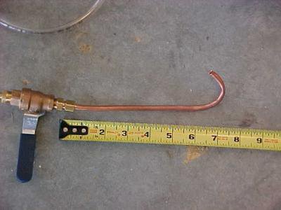 The Tiptronic transmission has a special tool for fluid. First you have to purchase the tool (expensive) or make one (inexpensive). The tool is the V.A.G.1924, runs about $300. You need the following tools and parts to start: 1. ATF fill tool 2. 7 (US) Quarts of Pennzoil Multi-Vehicle ATF 3. Torque wrench for 60 ft lbs 4. Torque wrench for 7.5 ft lbs (90 in lbs) 5. 17 mm allen bit 6. 8 mm allen bit 7. Torx 27 bit 8. Temperature meter with probe. I used an Oregon Scientific with a probe that has a 10 ft cord. 9. Porsche part 986 397 016 00 Paper gasket (Call Sunset Porsche, great guys) 10. Porsche part 986 307 403 00 ATF filter 11. Porsche part 986 397 016 00 rubber ring for fill plug 12. Kitty liter, you will spill 13. Socket set 14. Plenty of rags 15. Oil catch pan 16. Safety goggles First we assemble the filling tool out of parts you can find in Lowes or Home Depot type of homestores: 1. Hudson 1 gallon tank ($9.95) 2. Barbed fittings and 8 ft of tygon 3/8 clear hose. 3. 1/4 inch shut off valve - brass 4. 12 inch of flexible copper tube, 1/4" 5. Assemble as shown below and bend the tube per the picture. The steps are easy to follow: 1. Lift car off the ground and on jack stands. I need 16 inches on the stands to be comfortable. 2. Slide oil catch pan under fluid pan and remove drain plug with 8 mm allen bit 3. Remove the cross arm that traverses the fluid pan. Loosen only one bolt, remove the other. It will be easier for the next step and you can prop the arm to help catch the pan when the bolts are removed. 4. When the fluid has drained, secure drain plug back in and torque to 30 ft lbs. 5. Using the Torx 27 bit, remove all the screws crosswise. Move the cross arm out of the way as needed, but put back in a place where the pan will not fall. THE PAN STILL HAS FLUID in it, be careful 6. Remove pan carefully. The green gasket should still be attached to it. 7. Remove the two screws that hold the filter in place. Make sure the oil catch pan is underneath, the filter will have fluid as well. Remove filter. 8. Thinly coat some petroleum jelly on the suction collar of the ATF filter and install filter 9. Install new filter and screw the two screws to a torque of 4.5 ft lbs. 10. Empty the filter pan into the oil catch pan with all the waste oil. Place the filter pan on a flat surface and remove the gasket. 11. Set the plastic guard cap so the two windows are facing sideways. The holes will be used later for the fill tube and for the temperature probe. Notice how large they are. 12. Use the rags to clean the pan and the magnets in the pan. Set the magnets back to their original location. Here is a nice clean pan and magnets. 13. Place the new gasket on the pan. I used petroleum jelly thin coat on a few places to hold it in place. 14. Fit ATF pan back into transmission, tighten the screws crosswise to 7.5 ft lbs. It may be convenient to use the cross arm as a resting place while you re-attach the pan. 15. Remove the fill plug with the 17 mm allen key. Replace the ring gasket with the new one. 16. Fill the pressure tank with ATF fluid, make sure the valve is closed. Pump the tank to provide the pressure to move the fluid. The clear hose will show the red fluid filling it, and also you will see it running later. 17. Insert the "hook" end of the copper tube into the fill hole, and hook it into one of the holes mentioned before. Insert the temperature probe into the other hole, make sure it is secured. 18. Open the valve and let the ATF fluid begin to flow. You will have to add more fluid to the tank and keep it pumped. When the fluid begins to escape through the hole. It will drip, so close the valve. 19. Start the car. Open the valve to let more fluid into the ATF pan. Keep it pumped. Look at the temperature display on your probe. The temperature should not exceed 45 C. It begins at room temperature, so you got a few minutes. 20. Move the selector to position "P" and let idle for a a few seconds. When the fluid begins to emerge again from the filler tube, close the filling valve. 21. The engine should still be idling, keep an eye on the temp probe. With the brake pedal on, change the transmission through each position, holding the position for 10 seconds. 22. Open fill valve again until ATF fluid escapes from the hole. Make sure the temperature is higher than 30 C, and should be around 40C by now. Remove temperature probe and filler tube. 23. Replace the filler plug and torque to 59 ft lbs. 24. Turn engine off, and take car out for a test. :drive: 25. You are done, check for leaks, clean the spills (cat litter), and enjoy some smooth shifting.9 points
 -
 Note: Part numbers sometimes change without notice. Always double check with your supplier that you have the latest part numbers. Parts you will need: 3-4 liters 999 917 546 00 (Shell) Shell Transaxle (75W-90) or Mobil Mobilube PTX (75W-90) Approved Manual Transmission Oils 000 043 204 20 Mobil (Mobilube PTX) - 20 liter container 000 043 204 19 Shell (Transaxle) - 20 liter container 999 917 546 00 Shell (Transaxle) - 1 liter container Note: All are synthetic GL4 and GL5 rated (or "non-conventional processing") oils. GL oils have good light running properties because of their light low-temperature viscosity as well as a high level of temperature stability. Tools you will need: Tire ramps or jack 17 mm allen for the fill plug 16 mm triple square with a hole in the middle for the drain plug Note: Most later cars have an 10 mm allen type plugs - we recommend checking before you start. 3 quart oil catch pan Torque wrench (optional) Drain Transmission Oil Transmission oil should be changed when the engine/transmission has reached normal operating temperature. CAUTION - oil will be hot, take adequate precautions to avoid being burned. Use ramps or jack up the vehicle at the points provided. Remove underside panels to access the transmission. (Boxster owners you need to loosen the diagonal braces and then remove the transverse strut member. A little more work on a Boxster. When you put them back they need to have the bolts torqued to 48 ft lbs. (65 nm). See images Image 1 Image 2 Image 3 Image 4 Image 5 ) (images courtesy of scherb) Place oil collection pan under the transmission (at least 9 quarts). Always dispose of the waste oil in accordance with local legal requirements. Unscrew oil filler screw (1). Unscrew oil drain screw (2) and drain transmission oil. Wait about 20 minutes for all the old oil to drain. Fill Transmission Oil Clean oil drain and oil filler screw. Screw in oil drain screw. Tightening torque: 22 ft-lb. Fill with gear oil up to the bottom edge of the oil filler opening. Screw in oil filler screw. Tightening torque: 22 ft-lb. Install underside panels. Model/Capacity (approx.) Manual Transmission 911 Carrera (G96/00) - 2.7 liters 911 Carrera 4 (G96/30) - 2.7 liters GT3 - 3.3 liters Boxster (G86/00) - 2.25 liters Turbo - 3.0 (to 3.8) liters Front-axle Final Drive 911 Carrera 4 (Z96/00) - 1.5 liters Turbo - 1.5 liters8 points
 -
Filter location underneath the rear seat behind the driver side Replacing the filter: Recommended to do this job while the fuel tank is almost empty Fuel tank located underneath back seat Gain access to fuel filter need to flip back seat and look under the carpet Pull the seat buckle below the seat and flip the seat bottom Remove seat mount hinge, note you need special socket to fit the nuts Find below a round cut made on carpet, open Find round stainless steel caver with four screws, open it Then you will see the filter Use special tools to open the lock ring or use big flat screw driver with light hummer to remove the ring, slowly slowly, hit from different angles and corners to distribute the hummer pressure, Then disconnect fuel hose and electrical connection from top, be careful fuel house might be under pressure Note: petrol smells very strong and harmful, do this job in good ventilated area Note: there is a house connected between fuel filter on the left side of the fuel tank and fuel bump at the right side of fuel tank. Go to the right side of rear seat and flip the seat Find carpet cut same as left seat Remove seat mount hinge, note you need special socket to fit the nuts Open the stainless steel cover Find the plastic cover same as fuel filter housing Open the lock ring Then disconnect electrical connection and fuel house from top of plastic cover Be careful fuel might be under pressure Pull the plastic cover up, look down you will find a house that going to the filter at left side and some other house going to fuel bump, pull the house which is going to filter side several times back and forth to make sure it is the correct house going to filter side Then go to filter side on the left and remove the filter and note the house going to the right side, and pull to make sure that this is the right house going to left side After you are sure of the right hose Go back to right side are and tight the house with a string (or any available robe) before pulling the house this string will help you pull back the new house for the new filter back to the right side, Unplug the house go to left side and slowly pull the filter and un plug the other house and wire connection at the bottom of the filter side and make sure to tight the house and wire connection with strings to make sure not to fall down inside the tank bottom, Note: much petrol will comes out from filter After removing old fuel filter bring the new filter and first thing to do is to tight the string we all ready have from the old filter house side and insert in the fuel tank and pull slowly to right side Then connect back house and wire connection of the filter. Go to right side pull the string until you catch the new filter house and connect back to the plastic cover and put back all parts. Go to right side and put back every thing once an again.8 points
-
I got sick of not having cupholders in my Boxster. So I set out to find some. The options seemed to be OEM cupholders, either the clip on type, or the single DIN type. And we all know the problems with those - not secure enough fit, not accommodating large cups, etc. Also, the DIN type takes up an entire vertical DIN slot, making fitting double DIN GPS impossible. Other solutions seem to be to use a cutout for cups in the centre console box - which means the lid needs to stay open; and "ultimate cupholder" - which doesn't look OEM at all. So I was searching for generic cupholders on Ebay, and found this: http://cgi.ebay.com....=item439b780b6e And from a seller, the dimensions are: 7 7/16" long by 1" just the cover lid, assembly is 7" x 4 3/4" The width is as close to OEM fit for the Boxster as it gets, for a non-Porsche part! So I bought it. Realising that late model VWs like Passat and Jetta has the same console width as our Boxster, I then bought this: http://cgi.ebay.com....=item3ca672b7af It's entirely possible that other units like this http://cgi.ebay.com....=item3356ef534c would also fit. And before you start, get a rotary tool (like a Dremel). It's an absolute god send! Made things so easy. Here is the unit: Compared to another double DIN unit I originally planned for the mod: The difference is the newer one has a hi res screen. I actually rather liked the volume knob on the low res one. I put the cupholder and GPS unit together, with double sided tape, like this: You can also mount the cupholder on top, like this: I chose to go with the bottom fit, because I don't really like cups placed that high, and the bottom fit actually takes up a few mm less in height, which gives a better fit in the horseshoe frame. Speaking of frame, it's cut up, like this: There was a lip on the inner aspect of the lower border, this was cut to make room to increase the height. This, together with some slight sanding of the bottom of the cupholder was all that's required to make the height of the combo fit just right. Incredibly lucky! Note, you must get rid of the lower lip much as you can. Or the cupholder would be clamped too tight between the frame and the GPS, and it doesn't open when clamped tight. In the above picture, you can see I turned the OEM metal bracket around. This was necessary as the cupholder doesn't extend as deep as the OEM stereo, so the bracket support needs to come forward. You need to drill a hole in the original bracket to allow this. The reason will be very apparent when you actually do this. Here is a close up of the reversed bracket: The GPS antenna is simply placed near the alarm cover. Remove the alarm cover first, thread the GPS wire through, then just fish for it through the horseshoe frame. No need to remove anything else to place the GPS antenna. The thick wire attached to the GPS wire is the loom for my Head-Up-Display (another mod, for another day) :) The rest of the wiring here, with the unit ready to be pushed in: Here is the test fit: You can see that I will need a "n" shaped bezel to fill out the gap. This was obtained by modifying the Passat bezel that came with the GPS. The width is an exact fit, just like the cupholder (maybe 1mm longer, but I just left it). So I just sanded down the top border of the frame. And cut off the bottom border. I don't have a picture with the bottom border removed, only with the thinned top border: Press it in, it's a snug fit, not even sticky taped. And voooowwlaahhh!!!! OEM look!! From afar: With cupholder open: With a large "cup": In summary, get a genuine Jetta cupholder and an aftermarket Passat double DIN GPS! (not affliated with the seller/s, I promise) :)8 points
-
:welcome: For the Cayenne S and Turbo (V8) <----- FRONT 1 - Ignition bar module, cylinder 1, bank 1 2 - Ignition bar module, cylinder 2, bank 1 3 - Ignition bar module, cylinder 3, bank 1 4 - Ignition bar module, cylinder 4, bank 1 5 - Ignition bar module, cylinder 5, bank 2 6 - Ignition bar module, cylinder 6, bank 2 7 - Ignition bar module, cylinder 7, bank 2 8 - Ignition bar module, cylinder 8, bank 2
 8 points
 -
The most difficult part of changing the oil and Oil filter is actually removing all of the underbody panels that allow you to gain access to the Oil Pan Drain Plug and the Engine Oil Filter. I won't go through the details here as if you're tackling the oil change I'm sure you're mechanically competent enough to handle that on your own. The only real trick in changing the oil is handling the filter assembly correctly and making sure you drain the oil pan and not the front transaxle oil. I chose to drain the filter first by removing silver hex-head plug and letting the filter assembly drain. When completely drained, replace that and then remove the entire filter assembly (this saves you the hassles of cleaning up one filter's worth of oil) as you must turn the filter housing sideways to remove it from the compartment. Be sure and replace the O-Ring that comes at the base of the filter housing threads - your new filter should include one. Next, just drain the oil using the proper 18 mm wrench or socket on the Oil Pan Drain Plug....See pictures below.... Let drain completely, add some NEW Mobil 1 oil and then button everything back up as before....If you want to reset your service reminder, you'll need to go to your dealer and ask them to do it or get the Durametric software to do it yourself.8 points
-
 Note: Part numbers sometimes change without notice. Always double check with your supplier that you have the latest part numbers. Parts you will need: 1 ea 996 110 131 52 Air Filter or equal (BMC or K&N Filter) Tools you will need: 13 mm socket or wrench Regular screwdriver Phillips screwdriver Remove hexagon-head bolt M6 x 34. (13 mm wrench) Loosen the hose clamp on the throttle body and remove the connection of the sucking jet pumps (not present on early cars). Pull connecting plug off the mass air flow sensor by squeezing the connector clips. Then unclip the cable on the air cleaner housing. Subsequently unclip the oil filler snorkel. Remove the whole air cleaner housing out of the engine compartment. Unscrew the 7 (phillips) fastening screws on the air cleaner housing and remove the upper part of the air cleaner. Subsequently remove the cleaner element. Clean air cleaner housing. Insert new filter element and replace the upper part of the air cleaner housing (BMC filter shown). Tighten the 7 fastening screws. Place the air cleaner housing in the engine compartment again. Make sure that the rubber mount of the air cleaner housing is still seated in the body. Tighten the air cleaner housing with the fastening screw M6 x 34, the screw is tightened with 7.5 ft-lb. Clip in oil filler neck again.. Reconnect the intake pipes on the throttle body. Retighten the hose clamp. Subsequently insert the connection for the sucking jet pump (again, if present) and mount the spring band clamp. Fit the connecting cable and clip into the holder on the air cleaner. Push the connecting plug on the mass air flow sensor.8 points
 -
This is a DIY for anyone who wants to replace their crappy ~’99-’03 ignition switch with the upgraded switch/steering lock combo Porsche came out with in about ’04. I’ve seen this problem in both 996 and Boxster posts, so I suspect owners of both models may undergo this repair. I was able to do 90% of this from the driver’s seat rather than having to work under the dash. It may be possible from underneath, but I was glad not to have to do it. I’m sorry I don’t have pictures. Cameras just aren’t my thing. However, I will try to create very accurate descriptions in lieu. As far as DIYs go, it’s not so much difficult as time-consuming. The workspace is very tight; I’ve got small hands and forearms, but I still found it tough to reach certain bolts from time to time. Also, you need either very compact tools or the ability to improvise. For example, I put a Torx bit into a set of needle-nose Vise-Grips to get one screw out. Aside from these relatively minor issues, it’s not so bad. With that said, here we go… First things first: 1) Completely disconnect the battery. I can’t prove that total disconnection was necessary, but I also didn’t have the alarm go off suddenly. Better safe than deaf or shot by the neighbors. 2) Remove the rubber gasket around the ignition key. I could pull mine off just using my fingers. 3) Remove the left hand vent. There’s a nice writeup on this already; so I won’t repeat all of that here. http://www.renntech.org/forums/index.php?a...ost&id=6617 4) Once the vent is removed, remove the screw straight in the back back that holds the vent tube in place. 5) Now reach or crawl under the dash and remove the center horizontal vent tube under the steering column and the vertical one you just freed up in the step above. 6) Put on a long sleeve shirt. After working through the vent hole for a couple of hours, my forearm is pretty beat up today. I’ll save you the same realization… You’re now ready to start working on the issue at hand. 1) Reach to the back and disconnect the wiring harness from the ignition switch. It just goes straight off the back; no special clips there and don’t twist it. 2) Remove the immobilizer. It’s the black box on top of the steering lock housing. Unclip the little wiring harness on the front right. This one has a little catch on it so don’t just pull it out. There is a little plastic Phillips head near the key that you give a quarter-turn. Mine had ‘wings’ on the Phillips head that I could turn by hand. Once you’ve turned this, slide the immobilizer straight toward you along the top of the steering lock housing. That will free it up to remove. 3) Remove the key cylinder. Around the key hole is a silver beauty ring. Around the edge of that ring is a small hole. Make sure the hole is near the 7 o’clock position instead of near 1 o’clock. Mine had turned 180 degrees at some point and made this cylinder removal impossible until I figured that out. Insert your valet key (it’s just easier, but your regular remote key will work) and turn to position 1. Now stick a straightened paper clip (I used one of the larger, sturdier clips instead of a standard one) in as far as it will go. The cylinder should virtually fall out if you’ve done this right. If you’re having to tug on the key to pull it, try again. Carefully disconnect the electrical clip from the key cylinder. Leave both the key and clip in the cylinder and set the thing aside. 4) Disconnect the steering lock housing mounting screw near the key. This requires the same Torx bit you used to remove the side vent cover. I didn’t have a stubby Tork driver; so I clamped the bit into a pair of needle-nose Vise-Grips to get it loose. Once loosened, I could unscrew it by hand. Once the screw is out, swing the vertical mounting strut up and out of the way. 5) Disconnect the mounting bolt next to the steering column. A small 10mm ratchet worked for me. I didn’t have to put a wrench on the nut, but I had to use a bit of hand work to finally get the nut off and the bolt out. 6) Remove the steering lock housing. The trick here is that there is a spring-button that locks the housing into the steering column. You can see what you’re up against by looking at your replacement part. You depress the spring through a small hole on the steering column. I used a 2mm allen wrench to depress the button so that I could wiggle the housing out. Now you need to prep the new part. 1) Remove all of the clips from the old housing and attach them to the new one. There is a metal clip that secures the mounting screw near the key hole and two plastic wiring guide clips. I removed the plastic clips by punching out the center pins from the bottom (they are small and actually come completely out; don’t lose them) and then carefully squeezing the prongs until the clip came off. Attach them to the new part. 2) Put a little lubricant (just a light surface wiping, nothing more) on the housing surfaces that insert into the steering column. Install the new steering lock housing: 1) If the shiny silver steering lock ‘spear’ is extended from the housing, use a large flat blade screwdriver in the center of where the key cylinder would go and simulate turning the car on. This will retract the spear. 2) Insert the end of the housing into the steering column. This was the hardest part for me. I don’t know if the new part was just thousandths of an inch bigger or what, but it was 20 minutes of wiggling and jiggling that thing to get it in. Don’t forget that you will have to depress the little spring pin once it gets to the flange. I wasn’t sure I heard the spring pin pop into place in that hole; so I crawled under the dash to inspect it to be sure I seated the thing completely. 3) Replace the mounting screw near the key hole. By the way, I never replaced the 10mm bolt at the steering column. I couldn’t figure out how to restart the nut on the bolt, plus with that spring pin engaged, I can’t see how the housing could ever come out under normal use. 4) Reconnect the wiring harness to the ignition switch in the back. 5) Reconnect the immobilizer and its wiring clip. 6) Push the key cylinder in firmly (aligning it in the little guide on the top left of the steering lock housing) and pull the paper clip. It should be secured. Remove the key. Reconnect the tiny wiring clip to the key cylinder. 7) Reconnect the battery. 8) Start the car at this point to ensure that you’ve done everything right. If the car won’t start, something didn’t get reconnected properly or you have a different issue. Note: it is not necessary to have the headlight switch reassembled to start the car. If the car starts at this point, start replacing the rest of the stuff you pulled out. Start with the vent tubing. It was helpful to loosely attach the vertical tube with its screw before reconnecting the horizontal tube underneath. Once done underneath, tighten the vertical tube and replace everything else. Be very careful with the headlight switch reattachment as that lighted ring looks pretty fragile and the little bulbs have to fit exactly right into the plastic ring that covers it. Start ‘er up and hope that the new part is a thousand times more reliable than the one you replaced.7 points
-
Ok here is the deal with removing these things..... 1. First you must remove Both AC Vents, and the Upper Center Console... The strips are held in from screws behind the dash, but reaching them is a waist of time! 2. The 2 small strips will pop out with some force, just take a flat head screwdriver and tap it in behind the strip. The screws will pop out from the back of the dash... The dash is a hard plastic material and the screw heads are small so they will come right through the dash.. 3. The long piece across the passanger side was fun... Tape the dash will several pieces of tape to protect the dash in case you slip. These pieces have 2 layers to them.. take a flat head screwdriver and open the top part of the stip.. It will look like this once you peel off the top layer..you can see the top of the scew holes after you peel off the top layer Now my stereo installer had the next idea.. he took a small soldering gun like this... and heated up the head of the screw that is seen from the top side.. this made the area around the screw soft, and then I took the screwdriver behind the remaining strip and pried it right off.. it broke off to every screw head.. we just did this right along and 10 minutes later it was all out.. Be sure to not get the solder gun to close the the leather.. just keep it on for about 30 seconds.. it really is helpful if one guy holds the solder gun while the other removes the strip. The top piece is the stripped piece.. the bottom is the whole piece that was pulled out from the middle. Installing the new pieces was simple, a little silicone behind them helped the stay in place but its not needed..7 points
-
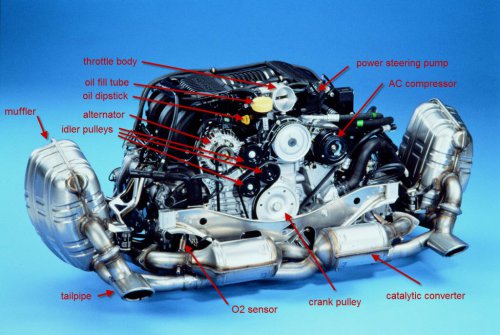 Cylinder Order (engine is turned 180 degrees for Boxster/Cayman) Cylinders 1,2,3 = bank 1 Cylinders 4,5,6 = bank 2 DME Sensors 1 - Mass air flow sensor 2 - Engine temperature sensor 3 - VarioCam valve 4 - Ignition coil 5 - Tank venting valve 6 - Secondary air pump 7 - Throttle potentiometer 8 - Idle speed air control valve 9 - Injection valve 10 - Knock sensors 11 - Hall-effect sensors 12 - Engine compartment temperature sensor 13 - Oil temperature sensor 14 - Resonance flap7 points
 -
These rubber "accordians" can crack over time. Fortunately the rubber piece is only around $60, and can be replaced easily. You'll need to set aside about an hour and a half if you haven't done this before. Tools needed: Flat-bladed screwdriver 4mm allen wrench Ratchet with short extension and 10mm socket Parts needed: The bellows Two plastic expanding fasteners (might come with the bellows) First, deploy your spoiler manually, and shut off the ingnition. No need to disconnect the battery. You will see, along the rear edge, four caps, as seen below. These pry out easily with your fingers or with a flat bladed screwdriver. No paint to worry about, just try not to mar the plastic. With the caps off you can access the 4mm allen head bolts: I found these to be a bit tight due to exposure to the elements, but I was able to get them off with an allen key. A long allen socket would work better. Once the bolts are out, the top tray (painted part) of the spoiler can be slid toward the rear and off. Put it somewhere where it won't be scratched. Now you can see the fasteners holding the top of the bellows to the spoiler. There are two explanding plastic fasteners, one on each corner, and several sliding hooks. I destroyed my plastic fasteners since my new bellows came with new ones. Just nipped them off with wire cutters. With the two plastic fasteners off you can disengage the hooks and detach the top of the bellows by sliding it to the right, and down. The top edge of the bellows is actually sandwiched between a long metal strip and the spoiler. The metal strip has the hooks that go through pre-cut holes in the bellows. View from below: With top of bellows detached: With the top of the bellows detached, open the engine lid. You will see several circular clips holding the bottom of the bellows to the engine lid: There is one under the fan, so you will have to detach the fan. Just three 10mm bolts. Just let it hang by the cable, out of your way. Be careful not to scratch your paint while removing the clips. In my case, the clips themselves had scratched the paint a bit. Fortunately this is one of the body areas that receives only a "rough" paint job from the factory anyway. Save those clips. It is not necessary to replace them. With the clips removed, you can pull the bellows out. As with the top, there is another frame piece running the length of the bottom of the bellows. This sandwiches the bottom of the bellows to the engine lid. The bellows has pre-cut holes for the nubs on the metal strip: Lay your old bellows alongside you new one, so that you can see how the top and bottom frame strips fit. Reassembly: Transfer your frame pieces to your new bellows. Then attach bottom of bellows to engine lid with the circular clips. Push those numbs through and get those clips up as tight as possible. The idea is to clamp onto the lower bellows edge. Re-attach the fan. Close engine lid Make sure the top frame piece hooks are threaded through the top of the bellows, push up through the corresponding holes in the spoiler, and slide to the left to secure. Make sure all of the hooks are engaged and snug. Then insert and secure the two plastic expanding fasteners in the corners. This step will confirm that you have the bellows and the spoiler snug and aligned properly. Now grab your painted spoiler top, and look under it to make sure the locking tabs are lined up. Push down, and slide toward the front of the car to lock the tabs. The top and bottom of the spoiler should mate very well. If you feel gaps around any edges, check and adjust. Finally, secure the top of the spoiler with the four allen screws. Put the plastic caps on, and manually raise and lower the spoiler to make sure you haven't left any tools in there...7 points
-
Hi, This is my first attempt to do a write up, hopfully this can help some people out. Here are the tools that you need: 1. hose clamp 2. spring-band clamp pliers 3. Torx socket 4. flexible head socket wrench First, you need you to remove underside panel to get to the coolant hoses. Then clamp shut coolant hoses with hose clamps. Then, undo drain plug at water guide housing and collect coolant. Next, undo pring-band clamps with pliers. From the top: the shop manual says to remove the right hand seat, which I did not do, but I think you will have more room to work around. Then, remove service cover at passenger compartment rear wall. To do this, first remove rear-wall lining, then undo 9 hexagon-head bolts (10mm) and remove cover. Those with the drive belt in-tact, need to remove the belt first, my belt was destroyed by the water pump (1st pic), so I skipped this step. After the belt is off, you can now take off the water pump using flexible wrench, socket is 10mm. There are 7 nuts in total if I remembered correctly, and the bottom 2 nuts I managed to get it off from the under side. After all the nuts are off, take the water pump off, and remove it. You can see in the pic that mine is very very broken. From here, install is just the reverse, make sure to put in the seal, otherwise it will leak. Put everything back and fill up the coolant see if it leaks ( if you have tools to pressure test it, even better!) drive around and let the bubble out, fill up, then you're done! :D B) make sure when you put the belt back, put belt in in this sequence: water pump, alternator, intermediate roller, power-steering, air-con compressor drive pulley, crankshaft, idler roller, then over the tensioning roller. Make sure you use correct socket size for your size, 2.7 uses 24mm, 2.5 uses 19mm.7 points
-
Yes that tube goes to the resonance flap. It's probably a really long tube right? That's the one that goes to the rear of the engine (front of car). From my above post: "In the diagram link below, the tubes you are talking about is #19, which goes into #21 (another hose) which then goes into the resonance flap: http://www.autoatlan...9-05/107-10.php" Yes the DIY link I posted has the procedure you need to remove the throttle body and t-plenum so you can reach behind the rear intake crossover and reconnect a new tube from the resonance flap to the change over valve in the position you indicate (hose/tube p/n 00004320501 qty 1) You might need a extendable mirror to see it.7 points
-
Just purchased a wind deflector and the mounting kit. Anyone have instructions on how to install it? Thanks. Edit -- please view the support topic here for details7 points
-
This is a short DIY about installing white LED daytime running lights on your 996. But first, thanks to Loren and all the other members who have posted DIY articles. Lately I have used them to do the PSE cutout mod, removed those ugly airbag stickers from my visors and changed the plugs at 30K. Got those lousy Bosch plugs out, installed NGKs and it runs like a different car. Smoother and more power. I found some white LED bars on Ebay that looked like they would fit just right in the air intakes. Search for item 390103978391 on Ebay, they go for about $50. In order to install the wiring you will have to remove the front bumper cover. I followed Loren's DIY on installing the third radiator. Also, you will have to remove the liner in the trunk area to get the wires through the bulkhead in back of the bumper. Here is a picture of the lights installed. I used double sided tape to mount them to the separator bar. Here the bumper cover is removed and I am running the wires up to the bulkhead. There is a round rubber plug just below and to the side of the latch that you can feed the wires through to the inside of the trunk compartment. Testing the lights before buttoning everything up. Everything back together. The only thing I have not completed is to find a source of switched 12 volts in the trunk area. If anyone out there knows of an easy way to pick it up I would appreciate hearing from you. Otherwise I will run the wire under the dash and pick up switched 12 there.7 points
-
Happy New Year everyone! It was cold and foggy here in Sacramento so I decided to do something about the yellowish headlights on my 03 996 C4S. I got the car about 3 weeks ago and it looks great but the headlights were somewhat yellowish. Looking at them closely, I noticed that there were very fine cracks and oxidation on the surface and decided to try to polish them. I found a "headlight lens restoration system" by 3M for $20 at Autozone. I removed the headlights and cleaned them well. Then I used a 500 grit disc (dry) on a drill to remove heavier scratches: The headlight looked completely ruined after sanding them with the 500 grit sand paper disc :o Then I used the 800 grit disc (dry) also on a drill to remove the scratches left by the previous disc: The headlight was not looking any better yet. The next step was to use a 3000 grit Trizact disc but I decided to wetsand using 2000 grit paper before: Then I used the 3000 grit disc (wet) on a drill. The disc is part of a thin foam pad so it stayed wet and worked nicely: The it was time to use the polishing compound on a foam pad. Just a little went a long way: This is the passenger's side headlight after polishing: And the driver's side headlight after polishing: I didn't take any photos before polishing them but I compared them after polishing only one and the difference was amazing. It removed all the yellowish tint from them. I'm going to buy some UV block for plastic tomorrow and see how long they stay clear and shinny. It took me about an hour and a half to do both headlights. So, if your headlights are not as clear as you would like, don't be afraid to sand them ;) Oscar7 points
-
Integrated Garage Door Opener DIY I got tired of forgetting to remove the garage door opener at Concours and getting points taken off, so I decided to integrate it into the center console. I got my inspiration from Kirby's Garage Door Opener DIY and added a few twists. I took the existing garage door opener from Genie and opened it up to use just the circuit board. This particular circuit board had lots of extra unused traces and holes that went back to were the switch was (probably for different enclosures), so I just picked 2 and ran about 5 feet of wire from each one. Then I put a little cap over the switch to prevent it from being pushed and wrapped the whole board in electrical tape. I wanted to put the circuit board transmitter as high in the car as possible to get the maximum sending range. I settled on putting the transmitter at the top of the drivers side A pillar, secured with some velcro. There is plenty of space under interior A pillar cover which goes over the transmitter with no problems. The 2 wires are run down the A pillar in the wire conduit that is there, and along the bottom of the drivers side of the dash to the center console. This arrangement gives me a 1.5 block range on the transmitter, which is further than I can see the house. The only downside to this arrangement is that you have to take off the A pillar cover to change the remote control battery. But this only need to be done every other year or more, so I don't think it is an issue. The parts that I used for the switch and its placement are from a 996 Targa. The batwing is called a Sole Switch Trim, P/N 996-552-335-01-01C and lists for $12.69. The Switch is called a Tip Switch, P/N 996-613-119-10-A05 and lists for 23.56. This switch is used to control the sunshade on the Targa. The plug blank is one I had laying around is probably under $5.00. Wiring the actual switch is pretty straight forward. There are 5 spades on the switch, 3 are used for the Garage Door Opener, and 2 are for the switch icon lighting. The 2 outboard vertical spades are for the lighting of the switch icon. Looking at the switch from the front, the spade on the left is the + lead, and the right spade is the - lead. I took lighting power from the seat heater switch lights. On those switches connector the brown wire is -, and the blue/red wire is +. The blue red wire is pigtailed between the 2 connectors, so that is the giveaway on it. I used inline cable splicers to connect the new leads. Back to the garage door switch, the center 3 spades are what are used for the wiring back to the remote control circuit board. The bottom horizontal spade is for one wire connection, and the 2 vertical spades above it are ganged together for the other wire connection. This way you can push the switch in either direction and the garage door remote will activate. So there you have it, another nice way to integrate your garage door opener into your 996. :) ONE LAST THING: Be sure to put in a fresh battery before you button up you work. A fresh battery can last 3-5 years under normal use! Otherwise, you may be opening up things much earlier to replace the battery.7 points